Second-Generation Channel Interface Processor (CIP2) Installation and Configuration 39
CIP2 Hardware Installation
Step 3 Remove the PCA cable connector (on the Y cable) from the PCA. (See Figure 19.)
Step 4 When you are finished with the task that required you to detach the PCA from the host
channel, reattach the PCA connector (on the Y cable) to the PCA.
Step 5 Place the select/bypass switch on the PCA connector in select mode. (See Figure 15 on
page 28.)
Step 6 Vary online all addresses assigned to the PCA. For instructions on how to vary addresses
online, refer to the documentation for your mainframe operating system.
Caution To prevent damaging the PCA connector on the CIP2 by unintentionally disconnecting the
Y cable from the PCA connector, provide adequate strain relief for the heavy bus and tag cables that
attach to the PCA.
Attaching the ESCON Cable
Following is the procedure for attaching the ESCON cable between the ECA and the host channel.
Caution To reduce the potential for problems, you should have an authorized service representative
or other qualified service person perform the following procedure. To prevent hardware problems
with your host processor, all the channel connections must be tight. A loose connection can cause
the host processor or its channel to halt. Every cable must be tightly seated in its mating connector.
Step 1 Make certain the ECA interface is shut down (using the shutdown interface command)
to prevent excessive error messages from being sent to the router log output. It is
recommended, but not necessary, to vary offline the host channel to which the ECA will
be attached. For instructions on how to vary the host channel offline, refer to the
documentation for your mainframe operating system.
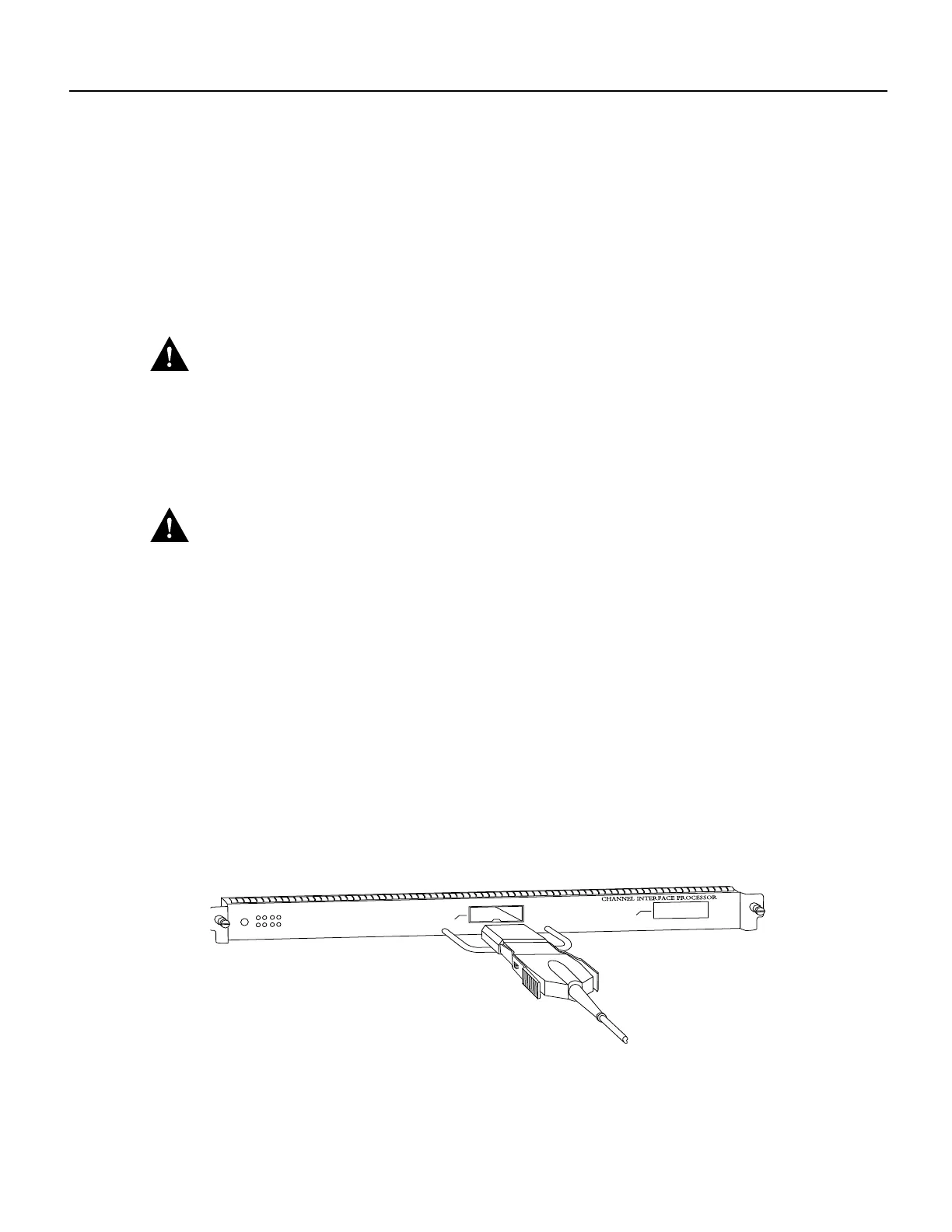
Step 2 Attach an ESCON cable between the ECA and the host channel. (See Figure 24.) Make
certain the ESCON cable plug “clicks” into place in the receptacle on the ECA. If not, the
connection will be incomplete and connection problems could result. It is best to visually
inspect the connection after you make it, rather than relying on an audible cue in a noisy
lab environment.
Figure 24 Connecting an ESCON Cable to the ECA
Step 3
Vary online the host channel. For instructions on how to vary the host channel online,
refer to the documentation for your mainframe operating system.
This completes the procedure for attaching an ESCON cable.
1
Single ECA
0
H2453
To an ESCON Director (switch)
or host CPU


