Appendix I GATM wiring chart 229
BCM50 Installation and Maintenance Guide
7
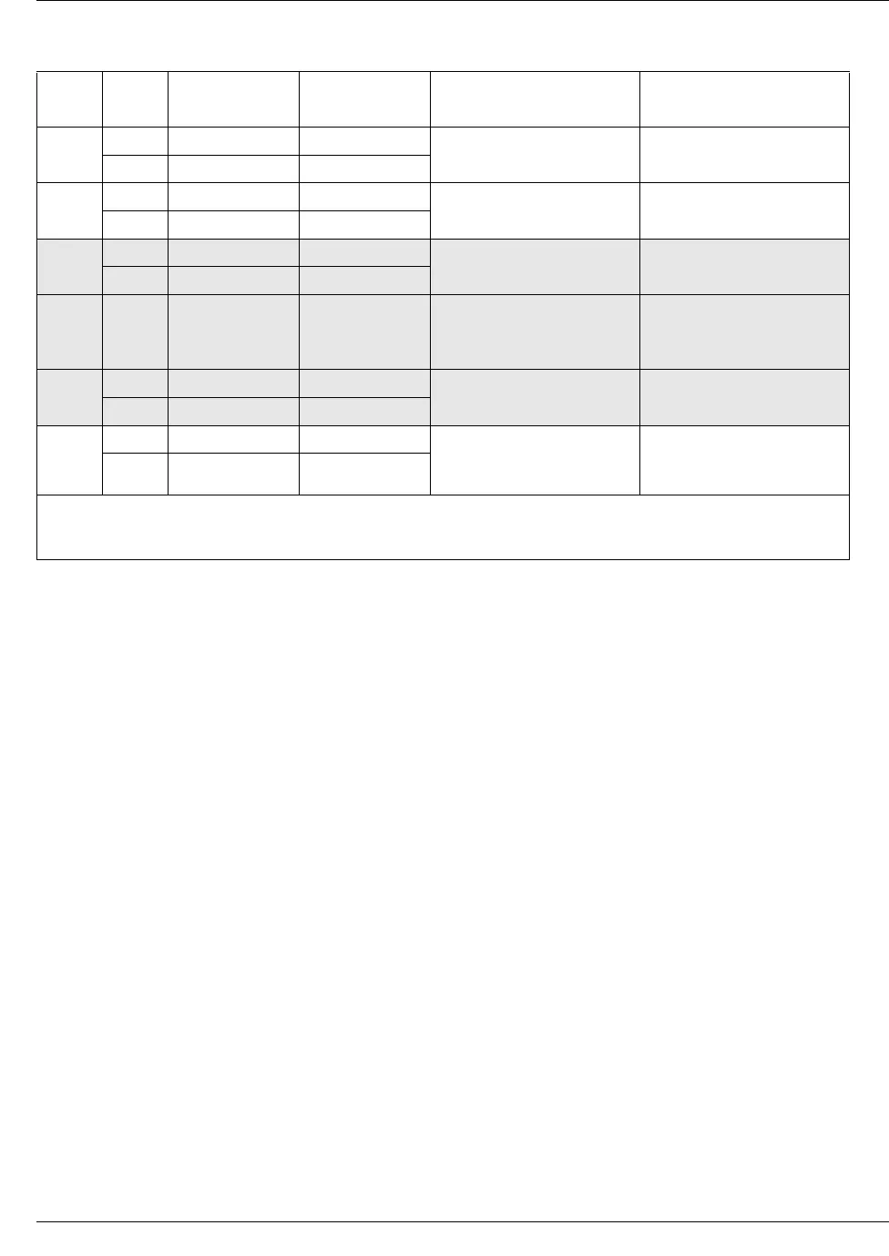
38 Tip Black-Green
075 105
13 Ring Green-Black
8
39 Tip Black-Brown
076 106
14 Ring Brown-Black
—
40 No connection Black-Slate
— —
15 No connection Slate-Black
.
.
.
.
.
.
.
.
.
.
.
.
.
.
.
.
.
.
—
49 No connection Violet-Brown
— —
24 No connection Brown-Violet
Aux
(see
Note)
50 Tip Violet-Slate
——
25 Ring Slate-Violet
Note: The AUX port supports full data speeds. When the line is in use by an analog device, the icon is lit on the
phone to indicate it is in use. If you try to seize the line using the phone, the display shows “in use”. Also, if a
power failure occurs, an analog set on line 1 activates (powered by the CO).
Table 46 GATM8 RJ-21 connector wiring (Sheet 2 of 2)
Line Pin Connection Wire color
Default line numbers on
Expansion port 1
Default line numbers on
Expansion port 2


