Appendix I GATM wiring chart 227
BCM50 Installation and Maintenance Guide
Appendix I
GATM wiring chart
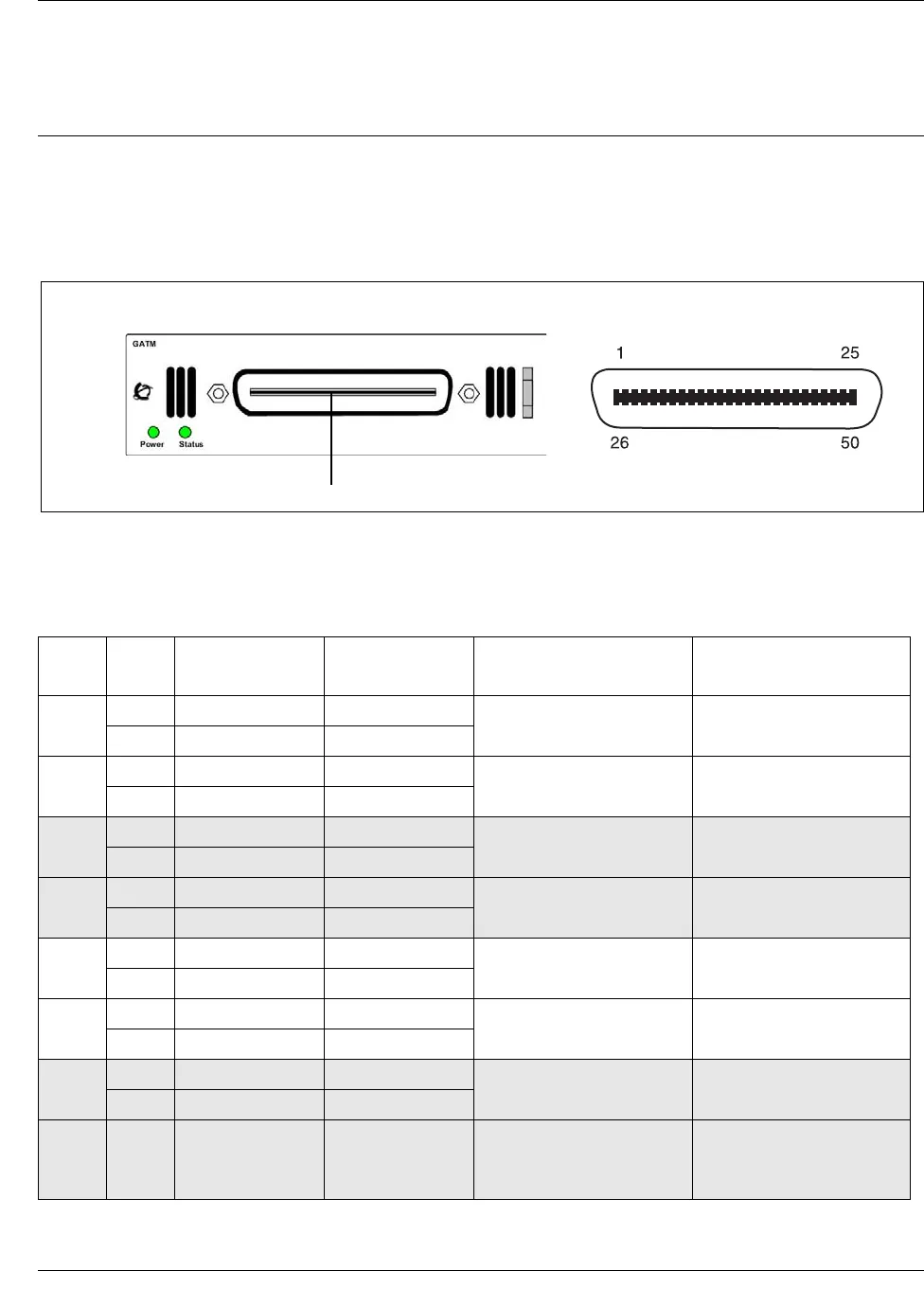
Analog telephone lines connect to the GATM4 or GATM8 through the RJ-21 connector on the
front of the media bay module (MBM). See the figure GATM RJ-21 connector on page 227.
Figure 95 GATM RJ-21 connector
The table GATM4 RJ-21 connector wiring on page 227 lists the wiring details for the RJ-21
connector on the GATM4.
Table 45 GATM4 RJ-21 connector wiring (Sheet 1 of 2)
Line Pin Connection Wire color
Default line numbers on
Expansion port 1
Default line numbers on
Expansion port 2
1
26 Tip White-Blue
065 095
1 Ring Blue-White
2
27 Tip White-Orange
066 096
2 Ring Orange-White
—
28 No connection White-Green
— —
3 No connection Green-White
—
29 No connection White-Brown
— —
4 No connection Brown-White
3
30 Tip White-Slate
067 097
5 Ring Slate-White
4
31 Tip Red-Blue
068 098
6 Ring Blue-Red
—
32 No connection Red-Orange
— —
7 No connection Orange-Red
.
.
.
.
.
.
.
.
.
.
.
.
.
.
.
.
.
.
RJ-21 pin outRJ-21 connector
GATM


