............ www.truemfg.com ............
True Food International Equipment, Inc.
19
19
of minutes. To disable one or more of the 6 scheduled defrosts, assign the value “---” (it is the value after “23.5”). Parameters DH1...DH6 are accessible both
in the setup (see §Conguration Parameters) and by keeping button pressed for 4 seconds during normal operation.
Synchronised defrost ■ . With DI2=DSY and when more units (models AR2-28x3xxx only) are linked to each other as per Fig. 3, synchronised defrosts of all
linked controllers will take place. The rst controller which will start defrost, will also get all other controllers synchronised.
Manual or remote defrost start. If DFM=TIM it’s possible to manually start a defrost, by pressing button
for 4 seconds. If DFM=RTC hold button down
for 4 seconds to display DH1, then press button
again for 4 seconds to manually start a defrost. Defrost may be also started remotely, if DI2=RDS, through
the making of the auxiliary contact DI2.
Defrost type. Once defrost has started, Compressor and Defrost outputs are controlled according to parameter DTY. If FID=YES, the evaporator fans are
active during defrost.
Defrost termination. The actual defrost duration is inuenced by a series of parameters.
Time termination ■ : T2=NO and T3 different from 2EU: the evaporator temperature is not monitored and defrost will last as long as time DTO.
Temperature monitoring of one evaporator ■ : T2=YES and T3 different from 2EU. In this case, if the sensor T2 measures the temperature DLI before the time
DTO elapses, defrost will be terminated in advance.
Temperature monitoring of two evaporators ■ : T2=YES, T3=2EU, OAU=2EU. This function is for the control of two independent evaporators and it switches
off the individual heating of the evaporator which gets to temperature DLI rst, waiting for the second evaporator to get to that temperature before the time
DTO elapses.
Resuming thermostatic cycle. When defrost is over, if DRN is greater than 0, all outputs will remain off for DRN minutes, in order for the ice to melt completely
and the resulting water to drain. Moreover, if probe T2 is active (T2=YES), the fans will re-start when the evaporator gets to a temperature lower than FDD;
Vice versa, if probe T2 is not active (T2=NO) or after defrost has come to an end, such condition does not occur by end of the time FTO, after FTO minutes
have elapsed the fans will be switched on anyway.
Caution: if DFM=NON or C-H=HEA all defrost functions are inhibited; if DFT=0, automatic defrost functions are excluded. During a high pressure alarm, defrost
is suspended. During defrost, high temperature alarm is bypassed.
CONFIGURATION PARAMETERS
To get access to the parameter conguration menu, press button ■ + for 5 seconds.
With button ■ or select the parameter to be modied.
Press button ■
to display the value.
By keeping button ■
pressed, use button or to set the desired value.
When button ■ is released, the newly programmed value is stored and the following parameter is displayed.
To exit from the setup, press button ■ or wait for 30 seconds.
PAR RANGE DESCRIPTION
SCL 1°C;
2°C;
°F
Readout scale.
1°C (with INP=SN4 only): measuring range -50/-9.9 … 19.9/80°C
2°C : measuring range -50 … 120°C
°F : measuring range -55 … 240°F
Caution: upon changing the SCL value, it is then absolutely necessary to re-congure the parameters relevant to the absolute
and relative temperatures (SPL, SPH, SP, ALA, AHA, etc..).
SPL -50..SPH Minimum limit for SP setting.
SPH SPL.120° Maximum limit for SP setting.
SP SPL... SPH Setpoint (value to be maintained in the room).
C-H REF; HEA Refrigerating (REF) or Heating (HEA) control mode.
HYS 1...10° OFF/ON thermostat differential.
CRT 0...30min Compressor rest time. The output is switched on again after CRT minutes have elapsed since the previous switchover. We
recommend to set CRT=03 with HYS<2.0°.
CT1 0...30min Thermostat output run when probe T1 is faulty. With CT1=0 the output will always remain OFF.
CT2 0...30min Thermostat output stop when probe T1 is faulty. With CT2=0 and CT1>0 the output will always be ON.
Example: CT1=4, CT2= 6: In case of probe T1 failure, the compressor will cycle 4 minutes ON and 6 minutes OFF.
CSD 0..30min Compressor stop delay after the door has been opened (active only if DS=YES).
DFM NON;
TIM;
RTC
Defrost start mode
NON : defrost function is disabled (the following parameter will be FID).
TIM : regular time defrost.
RTC : the defrost time is scheduled by parameters DH1, DH2...DH6.
DFT 0...99 hours Time interval among defrosts. When this time has elapsed since the last defrost, a new defrost cycle is started.
DH1
...
DH6
HH.M Scheduled time for defrost 1 to 6. HH hours from midnight, M tens of minutes. Accepted values go from 00.0 to 23.5. After
“23.5” the value is “---” that means “skipped defrost”. Example: DH1=8.3 means 8.30 AM.
DLI -50...120° Defrost end temperature.
DTO 1...120min Maximum defrost duration.
DTY OFF;
ELE;
GAS
Defrost type
OFF: off cycle defrost (Compressor and Heater OFF).
ELE: electric defrost (Compressor OFF and Heater ON).
GAS: hot gas defrost (Compressor and Heater ON).
DPD 0...240sec Evaporator pump down. At the beginning of defrost, defrost outputs (determined by DTY) are OFF for DPD seconds.
DRN 0...30min Pause after defrost (evaporator drain down time).
DDM RT;
LT;
SP;
DEF
Defrost display mode. During defrost the display will show:
RT : the real temperature;
LT : the last temperature before defrost;
SP : the current setpoint value;
DEF : “dEF”.
Refrigerating control (C-H=REF)
Heating control (C-H=HEA)
DDY 0...60min Display delay. The display shows the information selected with parameter DDM during defrost and for DDY minutes after
defrost termination.
FID NO/YES Fans active during defrost.
FDD -50...120° Evaporator fan re-start temperature after defrost.
FTO 0...120min Maximum evaporator fan stop after defrost.
FCM NON;
TMP;
TIM
Fan mode during thermostatic control.
NON : The fans remain ON all the time;
TMP : Temperature-based control. The fans are ON when the
compressor is ON. When the compressor is turned OFF, the fans
remain ON as long as the temperature difference Te-Ta is greater
than FDT. The fans are turned ON again with FDH differential.
(Te = Evaporator temperature, Ta = Air temperature);
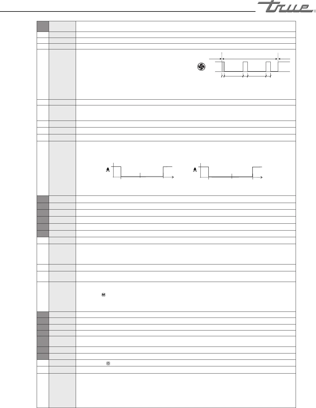
TIM : Timed-based control. The fans are ON when the compressor
is ON. When the compressor is OFF, the fans switch ON and
OFF according to parameteres FT1, FT2, FT3 (See Fig.2).
FDT -120...0° Evaporator-Air temperature difference for the fans to turn OFF after the compressor has stopped.
FDH 1...120° Temperature differential for fan re-start.
Example: FDT = -1, FDH=3. In this case, after the compressor has stopped, the fans are OFF when Te > Ta - 1 (FDT),
whereas the fans are ON when Te < Ta - 4 (FDT-FDH).
FT1 0...180sec Fan stop delay after compressor stop. See Fig. 2
FT2 0...30min Timed fan stop. With FT2=0 the fans remain on all the time.
FT3 0...30min Timed fan run. With FT3=0, and FT2 > 0, the fans remain off all the time.
ATM NON;
ABS;
REL
Alarm threshold management.
NON : all temperature alarms are inhibited (the following parameter will be ADO).
ABS : the values programmed in ALA and AHA represent the real alarm thresholds.
REL : the values programmed in ALR and AHR are alarm differentials referred to SP and SP+HYS.
SP
T[°]
SP+HYS+AHR
SP-ALR
ON
OFF
SP
T[°]
SP+AHR
SP-HYS-ALR
ON
OFF
ALA -50... 120°
Low temperature alarm threshold.
AHA -50... 120°
High temperature alarm threshold.
ALR -12... 0°
Low temperature alarm differential. With ALR=0 the low temperature alarm is excluded.
AHR 0... 12°
High temperature alarm differential. With AHR=0 the high temperature alarm is excluded.
ATI T1; T2; T3
Probe used for temperature alarm detection.
ATD 0... 120min
Delay before alarm temperature warning.
ADO 0... 30min
Delay before door open alarm warning.
AHM NON;
ALR;
STP;
Operation in case of high condenser alarm
NON : high condenser alarm inhibited.
ALR : in case of alarm, “HC” ashes in the display and the buzzer is switched on.
STP : in addition to the alarm symbols displayed, the compressor is stopped and defrosts are suspended.
AHT -50...120°
Condensation temperature alarm (referred to T3 probe).
ACC 0...52
weeks
Condenser periodic cleaning. When the compressor operation time, expressed in weeks, matches the ACC value programmed,
“CL” ashes in the display. With ACC=0 the condenser cleaning warning is disabled and CND disappears from Info Menu.
IISM NON;
MAN;
RTC;
HDD;
DI2
Switchover mode to second parameter set
NON : inhibition to use the second parameter group (the following parameter will be SB).
MAN : button
switches the two parameter groups over.
RTC : switchover to the second parameter group at STT time and back to the rst group at EDT time
HDD : automatic switchover to the second parameter group, when heavy duty conditions are detected.
DI2 : switchover to the second parameter group when the auxiliary DI2 input makes.
IISL -50... IISH
Minimum limit for IISP setting.
IISH IISL... 120°
Maximum limit for IISP setting.
IISP IISL... IISH Setpoint in mode 2.
IIHY 1... 10° OFF/ON differential in mode 2.
IIFC NON;TMP;
TIM
Fan control in mode 2. See FCM.
HDS
1...5 Controller sensitivity for the automatic switchover from Group I to Group II (1=minimum, 5=maximum).
IIDF
0...99 hours Time interval among defrosts in mode 2.
SB NO/YES Stand-by button
enabling.
DS
NO/YES Door switch input enabling (closed when door is closed).
DI2 NON;
HPS;
IISM;
RDS;
DSY
DI2 digital input operation
NON : digital input 2 not active.
HPS : when contact opens a condensing unit high pressure alarm occurs.
IISM : when contact makes the controller will use group 2 parameters.
RDS : when contact makes a defrost is started (remote control).
DSY : defrost synchronisation. The controllers, linked as per Fig. 3, will all start and end defrost together. The rst controller
in defrost will get defrost of all the others started. The last controller ending defrost will get defrost of all the others stopped.
OFF
ON
COMPR.
ON
COMPR.
ON
COMPR. OFF
FT1 FT2 FT3 FT3FT2
Fig.2 Time-optimised fan control (FCM=TIM)
Temperature alarm with relative thresholds,
refrigerating control (ATM=REL, C-H=REF).
Temperature alarm with relative thresholds,
heating control (ATM=REL, C-H=HEA).


