Shure T1 Body-Pack Transmitters
12Service Procedures
25C1016 (CC)
TP2
Test Points
TP1 Audio In, J104, pin 3, Model T1-P.
TP2 Audio In, J103, center conductor
of
1
/
4
-in. phone jack, Model T1-G.
TP3 Audio
TP4 Antenna Output
TP5 Intermediate Output
TP6 9 Vdc
TP7 5 Vdc
TP8 (+) Battery
TP9 (–) Battery
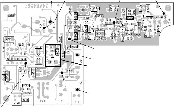
TP1 TP5 TP4
TP3
TP9 (–)
TP8 (+)
TP6
TP7
Limiter components
(not in all units)
Figure 3. Pcb Side 1
Display Checks
1. Connect the 9 Vdc power supply: the green LED should glow.
2. Reduce the power supply voltage to 6 Vdc: the red
LED should
glow.
3. Return the power supply voltage to 9 Vdc.
4. Verify that 9 Vdc 〈±0.35 Vdc) is present at
TP6.
5. Verify that 5 Vdc 〈±0.25 Vdc) is present at
TP7.
RF Alignment
A: RF Power and Frequency
1. Connect the 50 Ω output cable to the spectrum analyzer. Make
sure S101 is in the “Mute” position.
2. Set the spectrum analyzer as follows:
S Center Frequency: transmitter’s
S Span: 1
MHz
S Reference Level: +20 dBm
S Scale: 10 dB/div
3. The output power should measure 15 dBm ( ±2 dBm) taking into
account cable losses. If the power is within specification, skip to
step 6.
4. Adjust C217 for maximum (peak) output power on the spectrum
analyzer.
Note: Once the signal is close to its maximum, setting the spec-
trum analyzer scale (under the amplitude menu) to 2 dB/div may
make fine adjustments easier.
5. Adjust C215 for maximum output power on the spectrum analyz-
er. The output power should measure 15 dBm (±2 dBm) taking
into account cable losses.


