Shure T1 Body-Pack Transmitters
11
Service Procedures
25C1016 (CC)
S The Gain pot (R125) is preset to its midpoint.
S The 400 Hz high-pass and the 30 kHz low-pass filters on the
audio analyzer are activated.
Spectrum Analyzer
or
Frequency Counter
O
O
T1P (Connector J104)
Pins
1
2
3
4
T1G (
1
/
4
I
phone jack,
J103)
LED (red)
“Low Battery”
(D102)
Mute
switch
(S101)
Power On/Off
switch (S102)
“Power On”
LED (green)
(D101)
O
n
M
u
t
e
Battery
terminals
J101 –
J102 +
TP4
TP3
C215C217Y201
L209
R217
R125
R130
1
2
3
4
T1 (Tini “
Q-G,” J201—solder side)
T1 (Tini “Q-G”) pins:
1: Ground
2: +5 V
3: Audio
4: 20 kΩ to ground (connected
to pin 3 in the microphone)
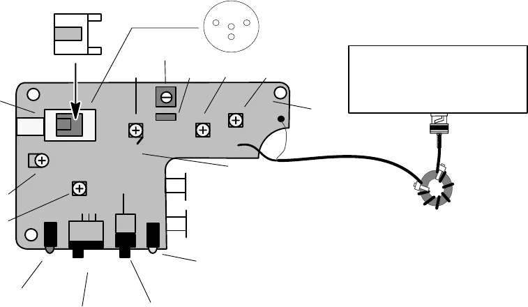
Figure 2. Pc Board: Key Parts Locations
Test Cable
Use a 50 Ω coaxial test cable to connect the pc board with various
test equipment (see Figure 2). To construct the 50 Ω test cable, see the
Wireless Service Equipment manual.
1. Unsolder the antenna lead from the pc board.
2. Attach the center conductor of the 50 Ω
RG174 cable to the antenna
solder pad, and the shield to ground.
3. Turn on the T1.


