OPERATING INSTRUCTIONS
4012/16 Diesel, February 1997 2
9
INITIAL STARTING OF THE ENGINE
WHEN FITTED WITH THE
REGULATEURS EUROPA 2100
HYDRAULIC GOVERNOR
NOTE: It is recommended that for initial
starting of new or overhauled engines, any
automatic starting or control systems are by-
passed and the engine is controlled
manually with the load disengaged, but with
the air shut-off valves manually set to the
'run' position (see Fig. 12).
R
emove the filler plug from the top face of
the governor and fill with oil to the line in the
sight glass (see Fig. 14). Refer to
Workshop Manual, Section AA41 for the
c
orrect grade of oil. Replace the plug.
Ensure that the fuel supply to the engine is
turned off.
Rotate the engine using the cranking device,
as described on page 55, in the correct
d
irection of rotation for two revolutions to
ensure that all working parts are free.
Disengage or remove the cranking device
immediately after use.
NOTE: When the engine is fitted with three
starter motors i.e. two electric and maybe
one air starter then on early engines one of
the starters may need to be removed to
enable the cranking device to be fitted.
The minimum and maximum speed stops
are factory set. Reduce the governor speed
setting by turning the hand wheel clockwise
until there is no further movement of the
output levers.
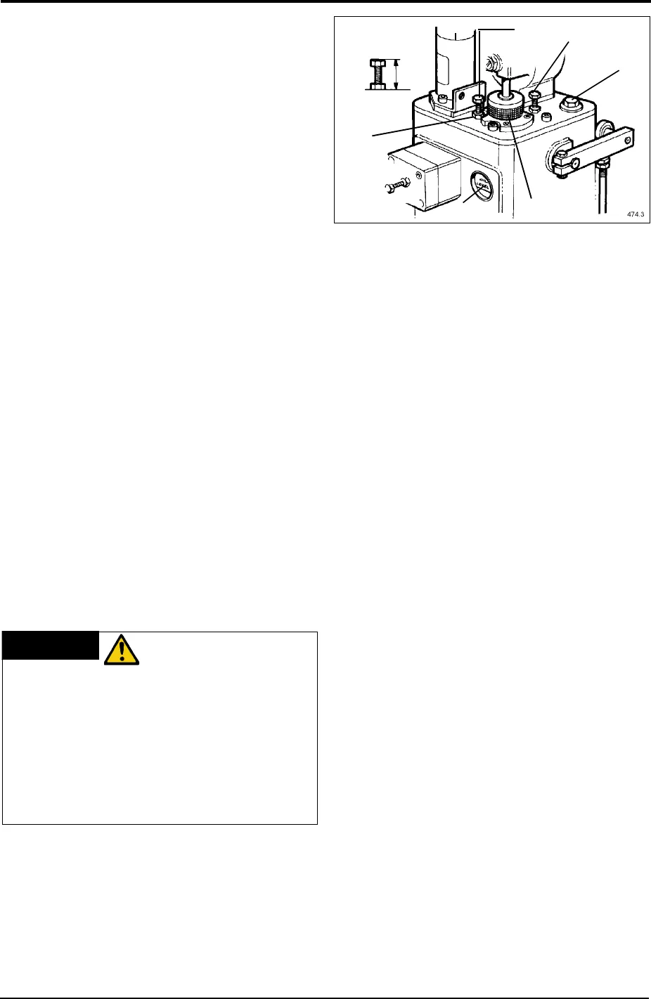
Key
(Fig. 14)
1 Locknut
2 Solenoid energised to stop
3 Minimum speed stop screw
4 Maximum speed stop screw
5 Oil filler plug
6 Hand control wheel
7 Oil level sight glass
Ensure the starting batteries are fully
charged. Energise the shutdown solenoid
('stop' position) and motor the engine over
on the starter until the oil pressure gauge
registers approximately 40 kPa (5 lb/in²).
Continue cranking for a further 10 seconds,
to ensure that the oil has reached the
turbochargers. Stop the engine by releasing
the start control and visually check the
engine for fuel or oil leaks, rectifying where
necessary. Turn on the fuel supply and bleed
the fuel system. Ensuring that the shutdown
solenoid is de-energised ('run' position)
crank the engine on the starter. The engine
should start and run up to the minimum
speed setting. Increase the engine speed by
turning the hand wheel anti-clockwise until
there is no further movement of the output
levers. With the engine running up to the
maximum speed setting, adjust the hand
wheel to obtain the desired operating speed.
Check the engine for fuel and oil leaks. Apply
load.
WARNING
UNDER NORMAL
CONDITIONS
GENERATING SETS MUST NOT BE RUN
AT LESS THAN THEIR NORMAL
OPERATING SPEED. OPERATION
BELOW THIS SPEED WILL DAMAGE
THE AUTOMATIC VOLTAGE
REGULATOR (AVR) THEREFORE
ISOLATE THE AVR BEFORE REDUCING
THE ENGINE SPEED.
Fig. 14
2
3
4
5
6
7
1