7. Valves in chilled water and condenser water
circuits open and water circulating properly. Do
not permit water warmer than 100 F to flow
thru cooler.
COMPRESSOR ROTATION — Set capacity control
(item 2, Fig. 3) to “Hold.” Press machine ON-STOP
and START buttons.
As soon as motor starts to turn, press machine
ON-STOP button. Check motor rotation thru sight
glass in motor end bell (Fig. 1). Motor rotation
must be clockwise when viewed from motor end. If
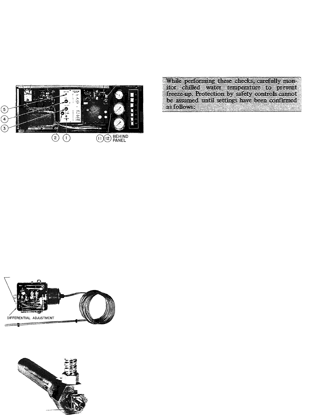
® © 0
© @
LEGEND
1. Motor Current Calibration Adjustment
2. Capacity Control Switch
3. Electrical Demand Adjustment
4. Thermostat (chilled water)
5. Throttle Range Adjustment
6. Condenser High-Pressure Cutout Switch (manual reset)
7. Cooler Low-Pressure Cutout Switch (manual reset)
8. Program Timer
9. Motor High-Temperature Cutout (manual reset)
10. Bearing High-Temperature Cutout (manual reset)
11. Low Oil Pressure Cutout
12. Economizer-Cooler Differential Pressure Switch
Fig. 3 — Control Center
not, reverse any 2 of 3 power leads coming into
motor starter and recheck rotation.
COMPRESSOR OPERATION
Press machine ON-STOP and START buttons and
let compressor come up to speed. Press machine
ON-STOP button and listen for any unusual sounds
coming from the compressor and transmission
housing as compressor coasts to a stop.
Program timer prevents rapid recycling of com
pressor and allows restart-15 minutes after stop.
Checking Safety Control Settings
add
Open main disconnect (all power off to starter
and controls). Set capacity control to “Hold.”
Place a clamp-on ammeter on one of the 3 starter
leads. Install jumper between [0] •
Close disconnect(s), start compressor and check oil
pressure and temperature (items 10 and 15, Fig. 1).
With compressor running, manually operate the
prewhirl vanes with the capacity control switch.
Do not exceed 100 percent full load amperage.
1. Set control 1 (chilled water low temperature
cutout) as indicated in Table 3.
2. Stop machine, open disconnect(s), remove
jumper and check controls 2 and 3 of Table 3.
3. Controls 4 and 5 do not require alteration of
factory settings. ;
4. Control 6 may require adjustment for operation
of unit at low design suction. Refer to Table 3.
Table 3 — Checking Safety Controls
SAFETY OR CONTROL DEVICE
RECOMMENDED SETTING
1. Chilled Water Low-Temperature Cutout
and Recycle Switch (Fig. 1)
-TEMPERATURE ADJUSTMENT
1. Set this switch to break at approximately 5 F below design chilled water
temperature, or at 36 F, whichever is higher
2. Set the differential at 10F±1 F so that whep the machine shuts down
automatically at approximately 5 F below the design chilled water tempera
ture it will restart at approximately 5 F above the design water temperature.
3. This control must break ahead of the cooler low-pressure cutout or the
machine will not recycle automatically
Perform checks 2 and 3 with machine stopped and jumper removed
2. Oil Heater Thermostat (Fig. 1)
.adjusting
"fcT'- / SCREW
»
LOCKING
SCREW
Set the oil heater thermostat to maintain a minimum oil reservoir temperature of
145 F at shutdown


