ISOLATION VALVE OPERATION
Opening — Compressor must be off and vessel
pressures equalized (see Return Refrigerant to
Normal Operating Condition, steps 1 thru 6).
^. Loosen packing nut 1/2 to 1 turn so valve stem
will rotate and slide smoothly in packing. Do
not let refrigerant trapped in valve body escape.
2. Hold stem in against line pressure and rotate
stem counterclockwise as far as possible.
3. Slide stem out of body.
4i Rotate stem clockwise in the out position, until
snug.
5. Tighten packing nut.
Closing
1. Loosen packing nut 1/2 to 1 turn so valve stem
will rotate and slide smoothly in packing. Do
not let refrigerant trapped in valve body escape.
2. Rotate valve stem counterclockwise as far as
possible.
3. Slide stem into valve until it bottoms.
4. Rotate stem clockwise, holding assembly in,
until it is tight (25 ft-lb).
5. Tighten packing nut.
TRANSFER REFRIGERANT FROM UTILITY
VESSEL TO UNI SHELL* from normal operating
condition.
1. Add manometer near charging valve 6.
2. Close isolation valves (27), (28), and (30).
3. Open valves 1, 3, 4, 6, 7 and 8.
4. Close valves 2, 5 and 9.
5. Ensure that pumpout condenser water is off.
6. Turn on pumpout compressor until liquid is
out of utility vessel.
7. Turn off pumpout compressor.
8. Close isolation valve (29).
9. Close valves 3 and 4.
10. Open valves 1,2, 5 and 6.
11. Turn on pumpout condenser water.
12. Run pumpout compressor until utility vessel
pressure reaches 25 in. Hg, ref 30-in. bar. (2.5
psia).
13. Turn off pumpout compressor.
14. Close valves 1, 2, 5 and 6.
15. Turn off pumpout condenser water.
TRANSFER REFRIGERANT FROM UNISHELL
TO UTILITY VESSEL* from normal operating
condition.
1. Open drain valve (26).
2. Wait one hour; close isolation valves (27), (28)
and (30).
3. Open valves 1,2, 5, 6, 7 and 8.
4. Close valves 3 and 4.
5. Ensure that pumpout condenser water is off.
6. Turn on pumpout compressor for 20 minutes.
7. Turn off pumpout compressor.
8. Close isolation valve (29).
Close valves 2 and 5.
10. Open valves 1, 3, 4 and 6.
11. Turn on cooler and condenser pumps and
pumpout condenser water.
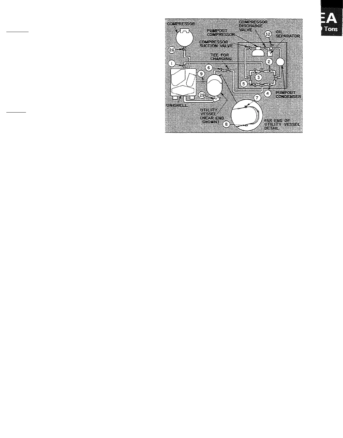
Fig. 2 — Pumpout System Schematic
(See Fig. 1 Legend for Item Ref)
12. Run pumpout compressor until unishell pres
sure reaches 25 in. Hg, ref 30-in. bar. (2.5
psia). Use dehydrator gage (34) for pressure
reading.
13. Turn off pumpout compressor.
14. Close valves 1, 3, 4 and 6.
15. Turn off pumpout condenser water.
UTILITY VESSEL EVACUATING PROCEDURE*
1. Close valves 1,2, 3, 4 and 9.
2. Open valves 5,6,1 and 8.
3. Open vent valve (32) and remove flare cap.
4. Turn off pumpout condenser water.
5. Operate pumpout compressor until manometer
reads 25 in. Hg, ref 30-in. bar. (2.5 psia).
6. Close valves 5, 6, 7 and 8.
7. Shut off pumpout compressor.
8. Close vent valve (32) and replace flare cap.
UNISHELL EVACUATING PROCEDURE*
1. Close valves 2, 4, 6 and 9.
2. Open valves 1, 3 and 5.
3. Open vent valve (32) and remove flare cap.
4. Turn off pumpout condenser water.
5. Operate pumpout compressor until manometer
reads 25 in. Hg, ref 30-in. bar. (2.5 psia).
6. Close valves 1, 3 and 5.
7. Shut off pumpout compressor.
8. Close vent valve (32) and replace flare cap.
RETURN REFRIGERANT TO NORMAL OPER
ATING CONDITION *
1. Ensure that opened vessel has been evacuated.
2. Close valves 3, 4 and 5.
3. Open valves 1,2, 6, 7 and 8.
4. Run water pumps.
5a. If unishell has been evacuated — Crack open
valve 4, gradually increasing pressure in uni
shell to 35 psig. Feed refrigerant slowly to
prevent tube freeze-up.
*See Fig 1 and 2 for all numbered references.


