3 PREPARATIONS FOR OBSERVATION
3-1-3 Selecting the Pinhole
Operate the pinhole tun-et (1) to select ttie pinhole corresponding to tiie pinhole number
indicated for
each
objective on tiie control panel.
(Refer
to
Section
2-1,
Scan Unit)
3-1-4 Selecting the Detection Mode
Set ttie detection mode selector slider to the designated position in accordance
with
Uie
fluochrome ofthe specimen to be
observed.
If
in
doubt about
Uie
setting,
refer to Section 4-
1-2, Adjusting the Scan Unit, in the Operation Manual and follow the prompts of the
[Microscope Configuration] window.
Example for reference
Fluochrome
FITC
Lucifer Yellow etc.
FITC + TRITC
FITC + PI etc.
PI
TRITC
Detection Channel
CHI
CH1/CH2
CH2
Detection Mode Selector Slider
Position
Pushed in
Middle position
* Pulled out
(Referto Section
2-1,
Scan Unit)
* In case of single-stained specimens, a brighter
image can be observed if ttie slider is set at the
pushed-in or out positions. Avoid the niiddle
position.
3-1-5 Engaging the Barrier Filter
Depending on the
fluochrome
of
the
specimen to
be
observed,
engage barrier
Alters
as
required.
The banier
filter
slider is engaged into the light
path
at ttie pushed-in position, and
disengaged at
Uie
pulled-out position.
* No image will appear if the slider is stopped between the positions. Always set at
correct position.
If in doubt about the
setting,
refer to Section
4-1-2,
Adjusting the Scan Unit, in the
Operation Manual and follow the prompts of the [Microscope Configuration]
window.
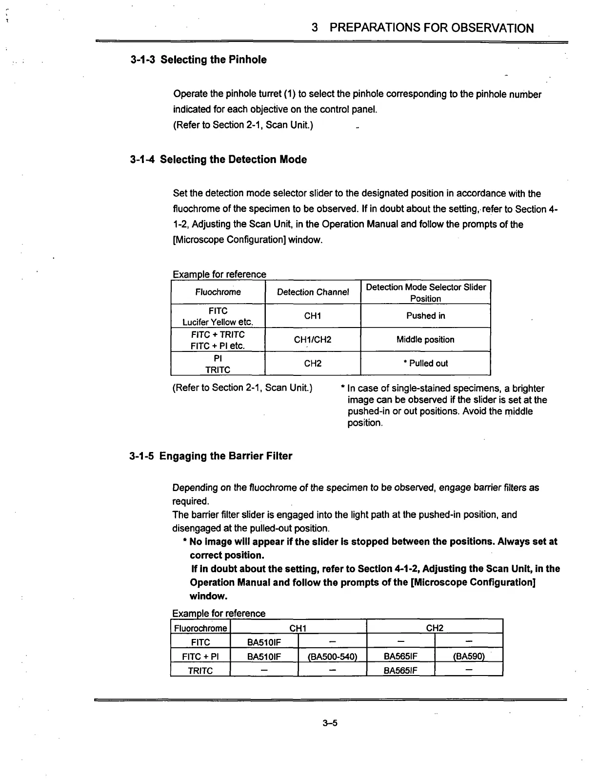
Example for reference
Fluorochrome
FITC
FITC + PI
TRITC
CHI
BA510IF
BA510IF
-
—
(BA500-540)
—
CH2
—
BA565IF
BA565IF
—
(BA590)
—
3-5


