2 MAIN UNITS AND DESCRIPTION OF CONTROLS
2 MAIN UNITS AND DESCRIPTION OF CONTROLS
Also referto Section 2-4, SYSTEM LAYOUT in the "INTRODUCTION TO FLUOVIEW manual.
2-1 Scan Unit
(5) Filter slider
cover screws
USBt IIIEKITr
0
(4) ND filter tun^t
(6) Laser line filter turret (only for
Kr and Ar laser combination)
"OPERATOR SERVICE"
(2) Detection mode _ (D Pinhole tun^t
selector slider
o(E)«
:iECTION WOE
Ofl OC
H. IR
H. H.
TR R.
OLYMPUS
FLUOVIEW
(D
&
(3) Banier filter slider
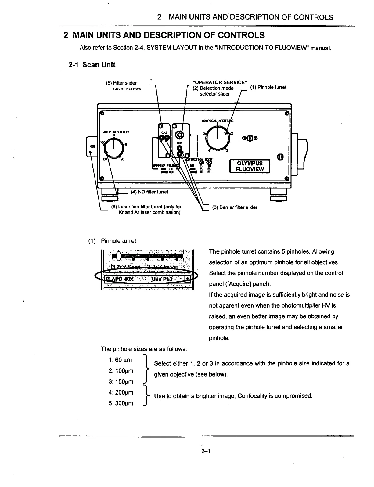
(1) Pinhole turret
The pinhole sizes are as follows
1:60nm
The pinhole turret contains 5 pinholes. Allowing
selection of an optimum pinhole for all objectives.
Select the pinhole number displayed on the control
panel ([Acquire] panel).
If the acquired image is sufficiently bright and noise is
not aparent even when the photomultiplier HV is
raised,
an even better image may be obtained by
operating the pinhole turret and selecting a smaller
pinhole.
2:
lOOum
3: 150nm
4:
200nm
5: 300nm
}
Select either 1, 2 or 3 in accordance with the pinhole size indicated for a
given objective (see below).
Use to obtain a brighter image, Confocality is compromised.
2-1


