Automation Processor with infiNET EX Crestron DIN-AP3MEX
12 • Automation Processor: DIN-AP3MEX Operations & Installation Guide – DOC. 7492B
Connectors, Controls, and Indicators
# CONNECTORS,*
CONTROLS, AND
INDICATORS
DESCRIPTION
1 PWR LED Dual-color green/amber LED,
indicates operating power
supplied from Cresnet network
or power supply, turns amber
while booting and green when
operating
2 NET LED Amber LED indicates
communication with the
3 Ground Captive screw terminal,
4 HW-R Button Recessed miniature push
button for hardware reset
button for software reset
(restarts the SIMPL program)
6 Antenna Connection for supplied
antenna or antenna extender
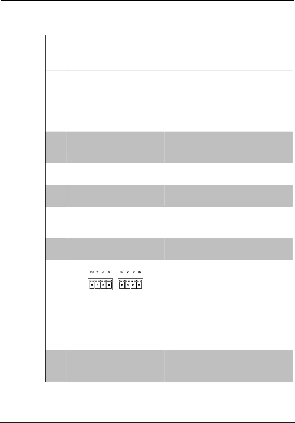
7 NET – 24 Y Z G
(2) 4-pin 3.5 mm detachable
terminal blocks, paralleled;
Cresnet port and 24 volt dc
power input
Cresnet master port
24: Power (24 Vdc)
Y: Data
Z: Data
: Ground
8 MSG LED Red LED indicates processor
has generated an error
(Continued on following page)


