MF1, MF2, PF1, PF2 Series Installation Instructions
8
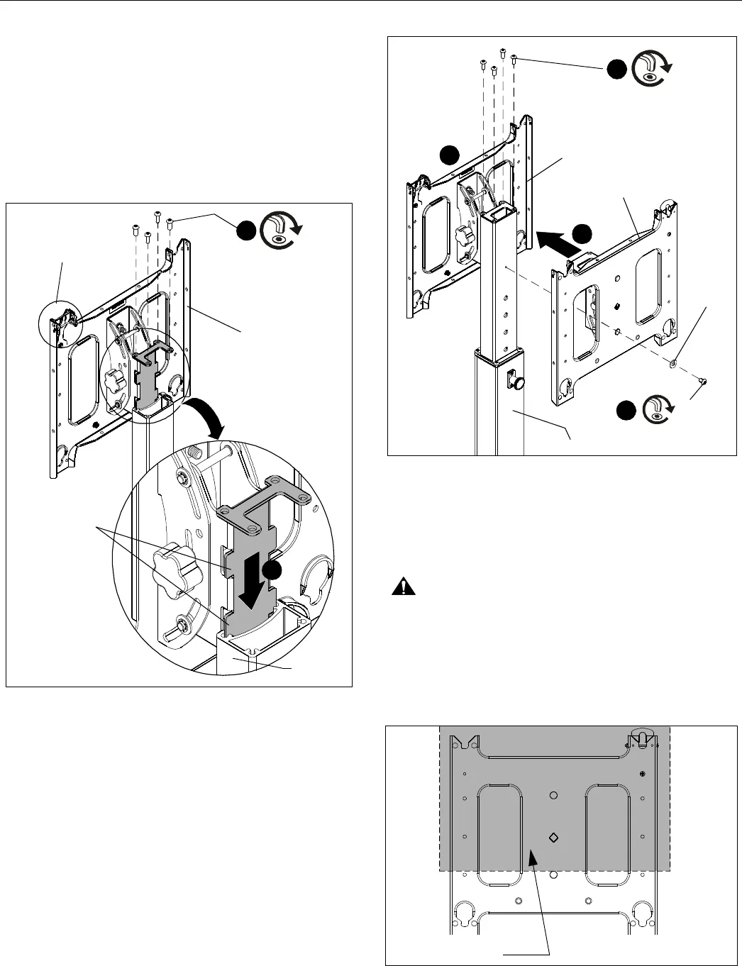
Attaching Single Head Assembly
IMPORTANT ! : When attaching head assembly ensure
that the ClickConnect lock is at TOP of head assembly,
and bracket tabs slide into the stand assembly. (See
Figure 8)
1. Slide head assembly (D) or (E) into the stand assembly.
(See Figure 8)
2. Attach head assembly to stand using four 5/16-18 x 3/4"
button head cap screws (M). (See Figure 8)
Figure 8
Attaching Dual Head Assembly
IMPORTANT ! : When attaching front head assembly
ensure that the ClickConnect lock is at TOP of head
assembly, and bracket tabs slide into the stand assembly.
(See Figure 8)
1. Slide front head assembly (D) or (E) into the stand
assembly. (See Figure 9)
2. Place back head assembly (D1) or (E1) on the back of the
stand assembly, and on top of the front head assembly.
(See Figure 9)
3. Use four 5/16-18 x 3/4" button head cap screws (M) to
fasten through both head assemblies. (See Figure 9)
Figure 9
4. Fasten through back head assembly (D1 or E1) and back of
stand assembly using one 1/4-20 x 3/8" button head cap
screw (K) and one 1/4" washer (P). (See Figure 9)
Adjusting Stand Height
CAUTION: ALWAYS remove the display(s) BEFORE
adjusting the height of stand.
1. Firmly grasp head assembly. (See Figure 10)
IMPORTANT ! : To avoid pinching hands, hold head
assembly when adjusting stand height.
Figure 10
(M) x 4
(PF1 Shown)
(Back view of stand)
ClickConnect
lock at TOP of
head assembly
Bracket Tabs
Stand
Assembly
(D) or (E)
2
1
1
2
4
3
(M) x 4
(K) x 1
(P) x 1
Back of stand
(PF2 shown)
(D)
(D1)
Grasp head assembly
within shaded area.
[PF Head
Assembly Shown]


