MF1, MF2, PF1, PF2 Series Installation Instructions
10
Tilting Display
The display(s) can be tilted up to 15
o
either backward or
forward from a straight upright position. In a dual stand, the
tilting is only restricted by the size of the display.
1. Turn knob counterclockwise on back of head assembly to
loosen the tilt. (See Figure 14)
Figure 14
2. Tilt display as desired, to a maximum of 15
o
either forward
or backward.
3. Turn knob clockwise to tighten display on head assembly.
(See Figure 14)
CAUTION: Tighten knob on back of head assembly to
prevent damage to the stand.
4. If leaving the display in a straight upright position, it is
recommended that a bolt (not provided) be placed through
the head assembly (See Figure 14) to lock the display into
the upright position.
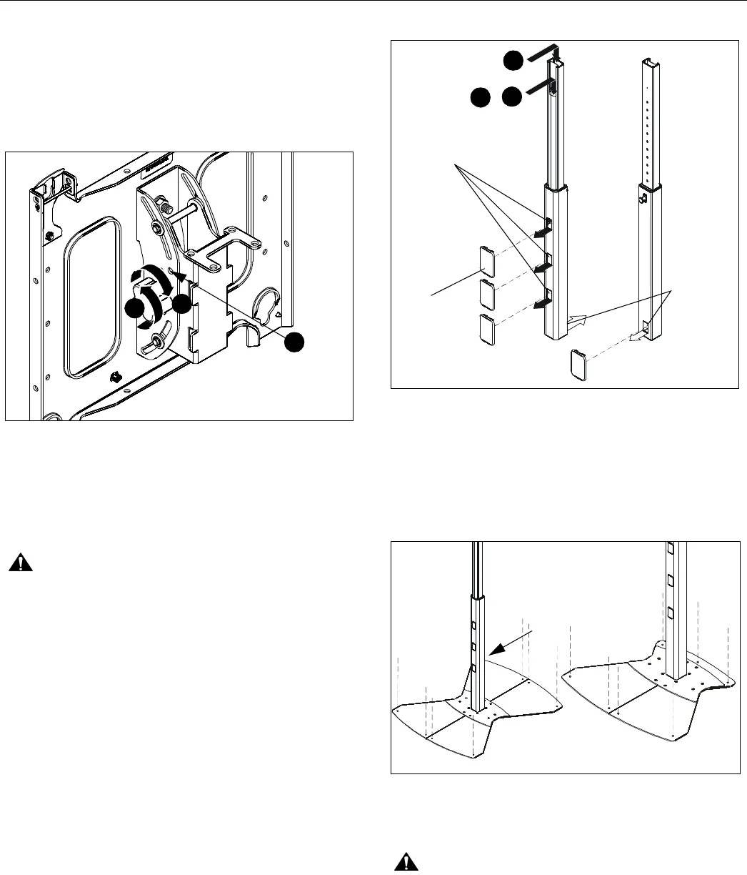
Cable Management
1. Signal cables can be run down the front flap of the center
post and out the front of the post at any of the openings.
(See Figure 15)
2. The display power cord can be run through the top and
down through the post to exit out the back. (See Figure 15)
3. Any accessory power cords can be run through the front
and down through the post to exit out the back. (See Figure
15)
4. Install the snap-on covers to any opening that is not being
used. (See Figure 15)
5. To remove the snap-on covers, grip the sides of the cover
in the middle and pull off. They can also be removed by
inserting a flat-blade screwdriver into the bottom slot and
prying them off.
Figure 15
Attaching Stand to Floor
The floor stand may be attached to the floor for a more
permanent installation.
1. Attach the floor stand to the floor using 5/16" or 3/8"
fasteners (not provided) which are appropriate for the floor’s
construction. (See Figure 16)
Figure 16
Using the Stand
CAUTION: This stand is intended for use only with the
products and maximum weights indicated: 125 lbs (56.70 kg)
for the MF1, 250 lbs (113.40 kg) for the MF2 [125 lbs
(56.70 kg) per faceplate]; 200 lbs (90.72 kg) for the PF1,
400 lbs (181.44 kg) for the PF2 [200 lbs (90.72 kg) per
faceplate]. Use with other products or products heavier than
the maximum weights indicated may result in instability
causing possible injury.
(PF1 Shown)
1
3
4
Place optional bolt
(not provided) here
to lock in an upright
position.
1
2
3
Exits for
signal cables
Snap-on
covers
Exit for
power
cables
(Front view
of center post)
(Rear
view of
center post)
Additional
fastener in
this corner
Dual Display Base
Single Display Base


