Protected by copyright. Copying for private or commercial purposes, in part or in whole, is not
permitted unless authorised by AUDI AG. AUDI AG does not guarantee or accept any liability
with respect to the correctness of information in this document. Copyright by AUDI AG.
❑ → Fig. (page 10)
J - Relay and fuse carrier in electronics box
❑ → Fig. (page 11)
K - Radiator fan control unit -J293-
❑ Fitted on left-side radiator fan (in direction of travel)
L - Injectors
❑ In fuel rail
❑ Removing and installing → Chapter (page 22)
❑ Injector, cylinder 1 -N30-
❑ Injector, cylinder 2 -N31-
❑ Injector, cylinder 3 -N32-
❑ Injector, cylinder 4 -N33-
The fuel injectors are high-pressure injectors. They inject fuel at high pressure (maximum approx. 120 bar)
directly into the cylinder.
M - 3-pin connector for knock sensor 1 -G61-
❑ → Fig. (page 11)
N - 3-pin connector for knock sensor 2 -G66-
❑ → Fig. (page 11)
O - Knock sensor 1 -G61-
❑ For cylinders 1 and 2
❑ Tightening torque: 20 Nm
❑ → Fig. (page 11)
P - Knock sensor 2 -G66-
❑ For cylinders 3 and 4
❑ Tightening torque: 20 Nm
❑ → Fig. (page 11)
Q - Oil pressure sender -G10-
❑ → Fig. (page 11)
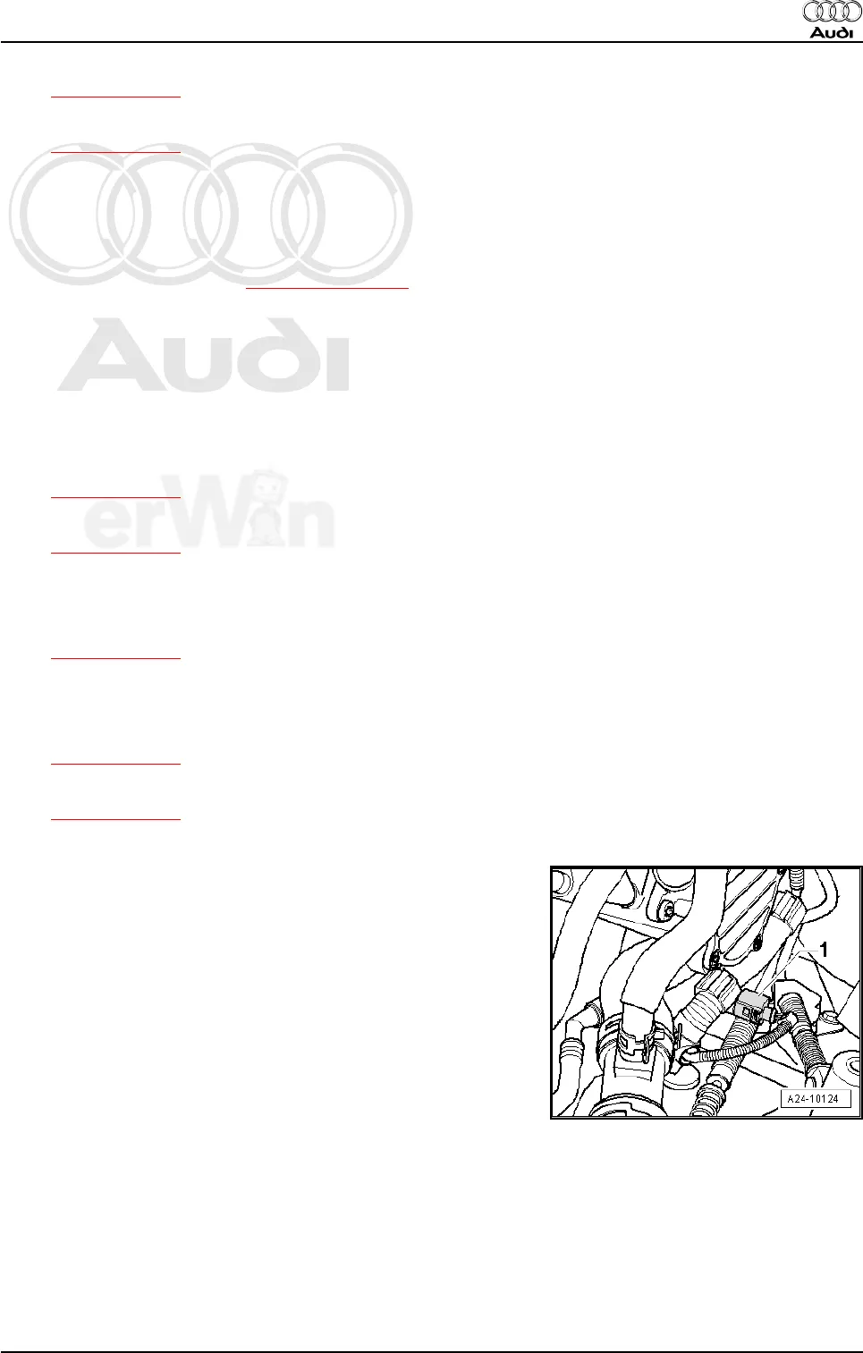
Coolant temperature sender -G62- -1-
Audi A3 2004 ➤
Direct petrol injection and ignition system (4-cyl. 2.0 ltr. 4-valve turbo) - Edition 11.2005
1. Servicing injection system 7


