» Connecting Your VCR or Laser Disc Player:
Use common RCA cables (not provided) to connect your VCR or laser disc player to your plasma monitor. To make these connections,
simply:
1. Turn off the power to your plasma monitor and VCR or laser disc player.
2. Connect one end of your RCA cable to the video output connector on the back of your VCR or laser disc player, connect the other
end to the Video input on your plasma monitor. Use standard RCA audio patch cords to connect the audio from your VCR or laser
disc player to your plasma monitor (if your VCR or laser disc player has this capability). Be careful to keep your right and left channel
connections correct for stereo sound.
3. Turn on the plasma monitor and the VCR or laser disc player.
Note: Refer to your VCR or laser disc player owner’s manual for more information about your equipment’s video output
requirements.
» Connecting Your DVD Player:
You can connect your plasma monitor to a DVD player. To do so, simply:
1. Turn off the power to your plasma monitor and DVD player.
2. Use a component video cable to connect your DVD player to the Y, Cb, and Cr inputs on your plasma monitor.
Or use the DVD player’s S-Video output. Use a standard S-Video cable to connect to the S-Video input on the plasma monitor.
3. Turn on the plasma monitor and the DVD player.
23
Installation
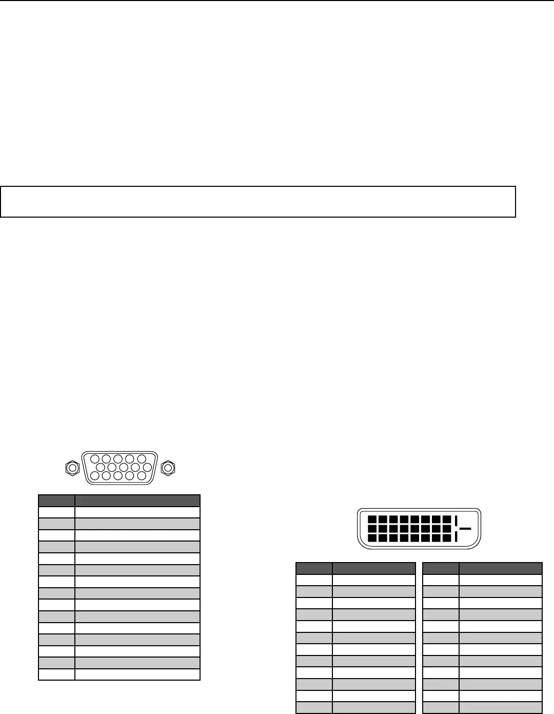
» Mini D-Sub Pin Assignment and Signal Levels
for 15-pin connector RGB (analog)
» DVI-D 24 -pin connector and Signal of the
RGB 3 Connector (DVI Connector)
The unit is equipped with a type of connector commonly used
for digital. (This cannot be used for an analog input.) (TMDS
can be used for one link only.)
5 4 3 2 1
15 14 13 12 11
10 9 8 7 6
1 2 3 4 5 6 7 8
9 10 11 12 13 14 15 1
6
20191817 21 22 23 24
RGB 3
Pin No. Signal (Analog)
1 Red
2 Green or sync-on-green
3 Blue
4 No connection
5 Ground
6 Red ground
7 Green ground
8 Blue ground
9 No connection
10 Sync signal ground
11 No connection
12 Bi-directional DATA (SDA)
13 Horizontal sync or Composite sync
14 Vertical sync
15 Data clock
Pin No. Signal (Digital)
1 T.M.D.S Data 2 -
2 T.M.D.S Data 2 +
3 T.M.D.S Data 2 Shield
4 No connection
5 No connection
6 DDC Clock
7 DDC Data
8 No connection
9 T.M.D.S Data 1 -
10 T.M.D.S Data 1 +
11 T.M.D.S Data 1 Shield
12 No connection
Pin No. Signal (Digital)
13 No connection
14 +5V Power
15 Ground
16 Hot Plug Detect
17 T.M.D.S Data 0 -
18 T.M.D.S Data 0 +
19 T.M.D.S Data Shield
20 No connection
21 No connection
22 T.M.D.S Clock Shield
23 T.M.D.S Clock +
24 T.M.D.S Clock -


