ITG User’s Guide
The contents of your product should contain the following items:
z
Internet Telephony Gateway 2 port or 4 port desk top version
z 100-240V Power Adapter
z 9-pin straight through RS-232 cable
z User’s guide
1.4
Front
Panel
The front panel of the ITG contains a push button and LED
indicators.
The
following
figure
illustrates the front panel of the ITG.
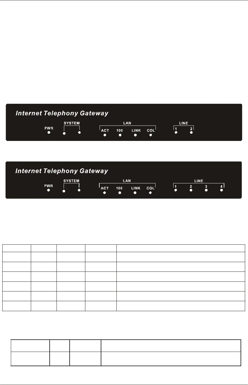
Figure 1-1 2 ports ITG Front Panel
Figure 1-2 4 ports ITG Front Panel
LED Indicators
When the ITG powers on, it switches the state of COL, LNK, 100 and ACT LED indicators in
red color per 200 ms in a manner shown in the following table
ACT
100
LNK
COL
Boot loader State
solid on
solid on
solid on
solid on
Execution start
blink
off
off
solid on
Memory test
blink
blink
off
solid on
Loading application code
blink
blink
blink
solid on
Loading TFTP loader code
blink
blink
blink
blink
Failed
loading application code and TFTP loader
off
off
blink
off
Memory test fail
The LED indicators on the front panel display the
current
status of the ITG as described in
the following table:
Indicator
Color
Activity
Indication
PWR
Green
On
Power is supplied to the gateway.
10
Overview


