1-30
GROUP 1-ENGINES
AND
EXHAUST SYSTEMS
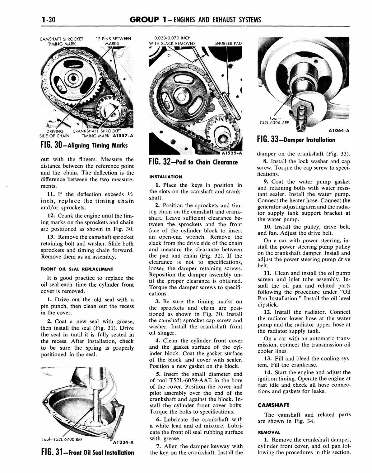
CAMSHAFT SPROCKET
TIMING MARK
12 PINS BETWEEN
MARKS
0.030-0.070 INCH
WITH SLACK REMOVED SNUBBER
PAD
DRIVING CRANKSHAFT SPROCKET
SIDE
OF
CHAIN TIMING MARK A1557-A
FIG. 30—
Aligning Timing Marks
out with the fingers. Measure the
distance between the reference point
and the chain. The deflection is the
difference between the two measure-
ments.
11.
If the deflection exceeds Vi
inch, replace the timing chain
and/or sprockets.
12.
Crank the engine until the tim-
ing marks on the sprockets and chain
are positioned as shown in Fig. 30.
13.
Remove the camshaft sprocket
retaining bolt and washer. Slide both
sprockets and timing chain forward.
Remove them as an assembly.
FRONT
OIL
SEAL REPLACEMENT
It is good practice to replace the
oil seal each time the cylinder front
cover is removed.
1.
Drive out the old seal with a
pin punch, then clean out the recess
in the cover.
2.
Coat a new seal with grease,
then install the seal (Fig. 31). Drive
the seal in until it is fully seated in
the recess. After installation, check
to be sure the spring is properly
positioned in the seal.
Tool-T52L-6700-BEE
A1234-A
FIG.
31-Front Oil Seal Installation
A1525-A
FIG.
32-Pad
to
Chain Clearance
INSTALLATION
1.
Place the keys in position in
the slots on the camshaft and crank-
shaft.
2.
Position the sprockets and tim-
ing chain on the camshaft and crank-
shaft. Leave sufficient clearance be-
tween the sprockets and the front
face of the cylinder block to insert
an open-end wrench. Remove the
slack from the drive side of the chain
and measure the clearance between
the pad and chain (Fig. 32). If the
clearance is not to specifications,
loosen the damper retaining screws.
Reposition the damper assembly un-
til the proper clearance is obtained.
Torque the damper screws to specifi-
cations.
3.
Be sure the timing marks on
the sprockets and chain are posi-
tioned as shown in Fig. 30. Install
the camshaft sprocket cap screw and
washer. Install the crankshaft front
oil slinger.
4.
Clean the cylinder front cover
and the gasket surface of the cyl-
inder block. Coat the gasket surface
of the block and cover with sealer.
Position a new gasket on the block.
5.
Insert the small diameter end
of tool T52L-6059-AAE in the bore
of the cover. Position the cover and
pilot assembly over the end of the
crankshaft and against the block. In-
stall the cylinder front cover bolts.
Torque the bolts to specifications.
6. Lubricate the crankshaft with
a white lead and oil mixture. Lubri-
cate the front oil seal rubbing surface
with grease.
7.
Align the damper keyway with
the key on the crankshaft. Install the
Tool-
T52L-6306-AEE
A1064-A
FIG.
33—Damper Installation
damper on the crankshaft (Fig. 33).
8. Install the lock washer and cap
screw. Torque the cap screw to speci-
fications.
9. Coat the water pump gasket
and retaining bolts with water resis-
tant sealer. Install the water pump.
Connect the heater hose. Connect the
generator adjusting arm and the radia-
tor supply tank support bracket at
the water pump.
10.
Install the pulley, drive belt,
and fan. Adjust the drive belt.
On a car with power steering, in-
stall the power steering pump pulley
on the crankshaft damper. Install and
adjust the power steering pump drive
belt.
11.
Clean and install the oil pump
screen and inlet tube assembly. In-
stall the oil pan and related parts
following the procedure under "Oil
Pan Installation." Install the oil level
dipstick.
12.
Install the radiator. Connect
the radiator lower hose at the water
pump and the radiator upper hose at
the radiator supply tank.
On a car with an automatic trans-
mission, connect the transmission oil
cooler lines.
13.
Fill and bleed the cooling sys-
tem. Fill the crankcase.
14.
Start the engine and adjust the
ignition timing. Operate the engine at
fast idle and check all hose connec-
tions and gaskets for leaks.
CAMSHAFT
The camshaft and related parts
are shown in Fig. 34.
REMOVAL
1.
Remove the crankshaft damper,
cylinder front cover, and oil pan fol-
lowing the procedures in this section.


