PART 1-2-MILEAGE MAKER SIX
1-29
UNDERSIDE
OF
SPRING RETAINER
SURFACE
OF
SPRING
PAD
A104 7-A
FIG.
27—Valve Spring Assembled
Height
2.
Install each valve (Fig. 26)
in
the valve guide from which
it
was
removed or to which it was
fitted.
In-
stall
a
new stem seal on the valve.
3.
Install the valve spring assembly
over the valve. Install the spring re-
tainer and sleeve.
4.
Compress the spring and install
the retainer locks (Fig. 25).
5.
Measure the assembled height
of the valve spring from the surface
of the cylinder head spring pad to the
underside
of
the spring retainer with
dividers (Fig. 27).
Check the dividers against
a
scale.
If
the
assembled height
is
greater
than
the
specified limit, install
the
necessary 0.030-inch thick spacer(s)
between the cylinder head spring pad
and the valve spring to bring the as-
sembled height to the recommended
dimension. Do not install spacers un-
less necessary. Use
of
spacers
in
ex-
cess
of
recommendations will result
in overstressing the valve springs and
overloading the camshaft lobes which
could lead
to
spring breakage
and
worn camshaft lobes.
6. Install the temperature sending
unit.
7.
Using a new gasket coated with
water resistant sealer, install
the
Tool-T52L-6316-FEE
h
A1041-A
FIG.
28—Damper Removal
thermostat and coolant outlet elbow.
Torque the retaining bolts to specifi-
cations.
VALVE STEM SEAL
REPLACEMENT
1.
Remove the air cleaner and the
valve rocker arm cover. Remove the
applicable spark plug.
2.
Crank the engine until the ap-
plicable piston
is
on TDC after the
compression stroke. Be sure that both
valves are closed.
3.
Remove the push rod.
4.
Install an air line with an adapt-
er in the spark plug hole.
5.
Push
the
rocker arm
to one
side and secure
it in
this position
(Part
1-4,
Fig. 31).
To
move
the
rocker
arm on
either
end of the
shaft,
it
will be necessary to remove
the retaining
pin and
washers
and
slide the rocker arm off the shaft.
6. Turn on the air supply. Using
the valve spring compression tool
shown in Part 1-4, Fig. 31, compress
the valve and remove the valve spring
retainer locks, the sleeve, spring re-
tainer, and the valve spring.
7.
Remove
the
valve stem seal
(Part 1-4, Fig. 32).
8. Install
a
new valve stem seal.
Place the spring in position over the
valve. Install the spring retainer and
sleeve. Compress
the
valve spring
and install the valve spring retainer
locks.
9. Apply Lubriplate
to
both ends
of the push rod. Install the push rod
making sure the lower end of the rod
is positioned
in
the tappet push rod
cup.
10.
Remove the wire securing the
valve rocker arm and slide the rocker
arm into position.
If an
end valve
rocker arm was removed, slide
it
into position on the shaft and install
the washers and retaining pin. Turn
off the air and remove the air line and
adapter. Install the spark plug and
spark plug wire.
11.
Adjust the valve lash.
12.
Install
the
valve rocker arm
cover
and
connect
the
spark plug
wires.
Install the air cleaner.
CYLINDER FRONT COVER
AND TIMING CHAIN
REMOVAL
1.
Drain the cooling system and
crankcase.
On
a
car with an automatic trans-
mission, disconnect the transmission
oil cooler lines
at
the radiator.
2.
Disconnect the radiator upper
hose at the radiator supply tank and
the radiator lower hose
at
the water
pump. Remove the radiator.
3.
Remove the fan, drive belt, and
pulley.
On
a car
with power steering,
remove
the
power steering pump
drive belt. Remove the power steer-
ing pump pulley from the crankshaft
damper.
4.
Remove
the cap
screw
and
washer from the end
of
the crank-
shaft, then remove the damper (Fig.
28).
5.
Remove the
oil
level dipstick.
Remove the oil pan and related parts
by following
the
procedure under
"Oil Pan Removal." Remove the oil
pump screen and inlet tube assembly.
6. Disconnect the heater hose
at
the water pump. Disconnect the gen-
erator adjusting
arm and
radiator
supply tank support bracket
at the
water pump. Remove the water pump.
7.
Remove the cylinder front cov-
er and discard the gasket.
8. Remove
the
crankshaft front
oil slinger. Rotate the crankshaft in
a
clockwise direction (as viewed from
the front) to take up the slack on the
left side of the chain.
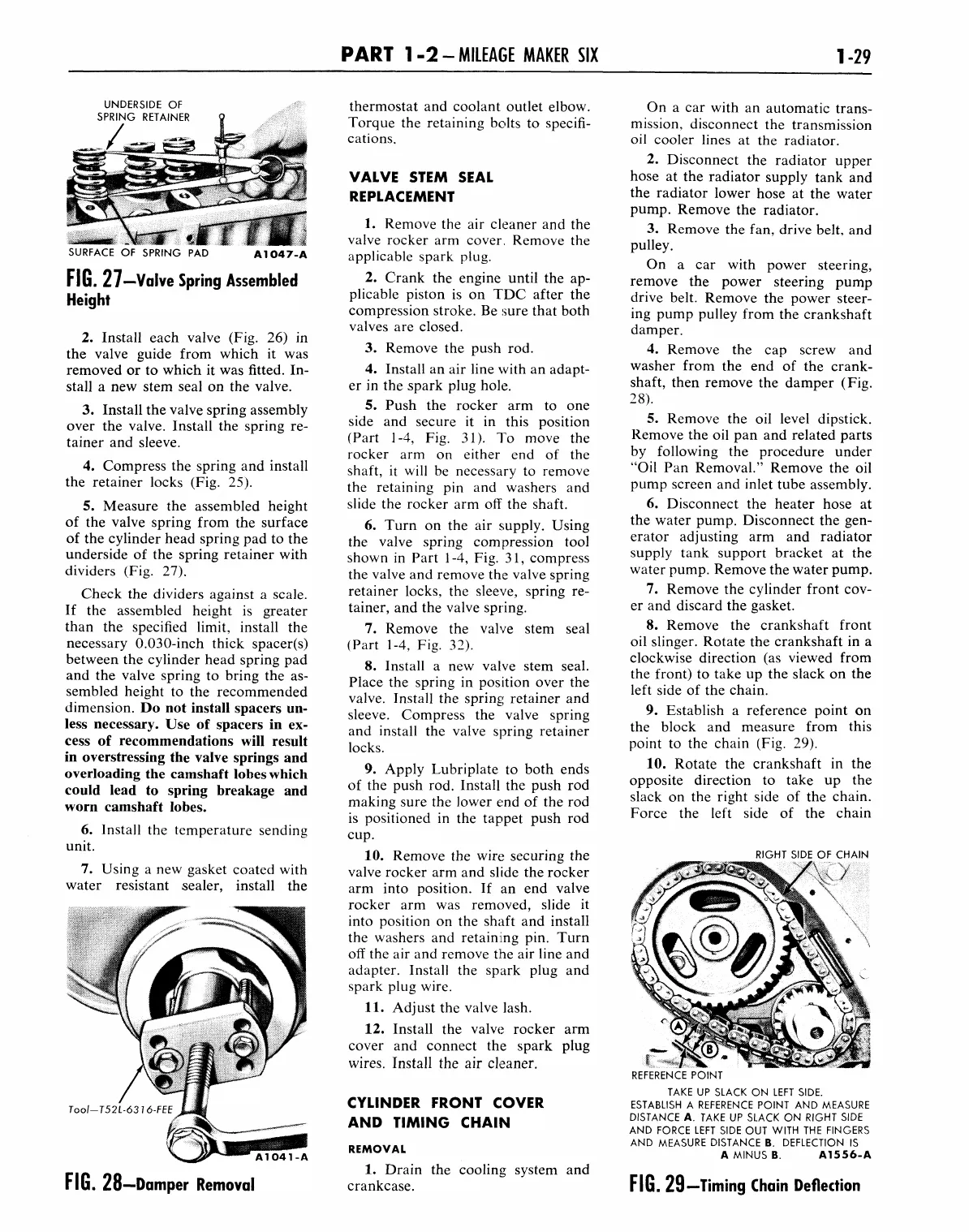
9. Establish
a
reference point on
the block
and
measure from this
point
to
the chain (Fig. 29).
10.
Rotate the crankshaft
in the
opposite direction
to
take
up the
slack on the right side
of
the chain.
Force
the
left side
of the
chain
RIGHT SIDE OF CHAIN
f
*-•
REFERENCE POINT
TAKE UP SLACK ON LEFT SIDE.
ESTABLISH
A
REFERENCE POINT AND MEASURE
DISTANCE A. TAKE UP SLACK ON RIGHT SIDE
AND FORCE LEFT SIDE OUT WITH THE FINGERS
AND MEASURE DISTANCE
B.
DEFLECTION
IS
A MINUS B.
A1556-A
FIG.
29—Timing Chain Deflection


