Step 1: Locate the female DB-15 connector. The location of the female DB-15
connector is shown in Figure 1-4.
Step 2: Align the VGA connector. Align the male DB-15 connector on the VGA screen
cable with the female DB-15 connector on the external peripheral interface.
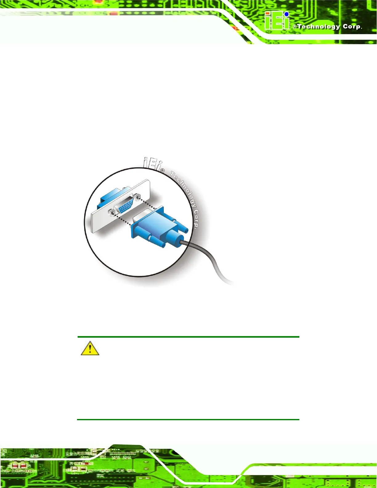
Step 3: Insert the VGA connector. Once the connectors are properly aligned with the
insert the male connector from the VGA screen into the female connector on the
UPC-V315-QM77. See Figure 3-35.
Figure 3-35: VGA Connector
CAUTION:
It is suggested that not to open the rear cover and replace any
components. If the components fail, it must be shipped back to IEI to
be replaced. If the system has failed, please contact the system
vendor, reseller or an IEI sales person directly.


