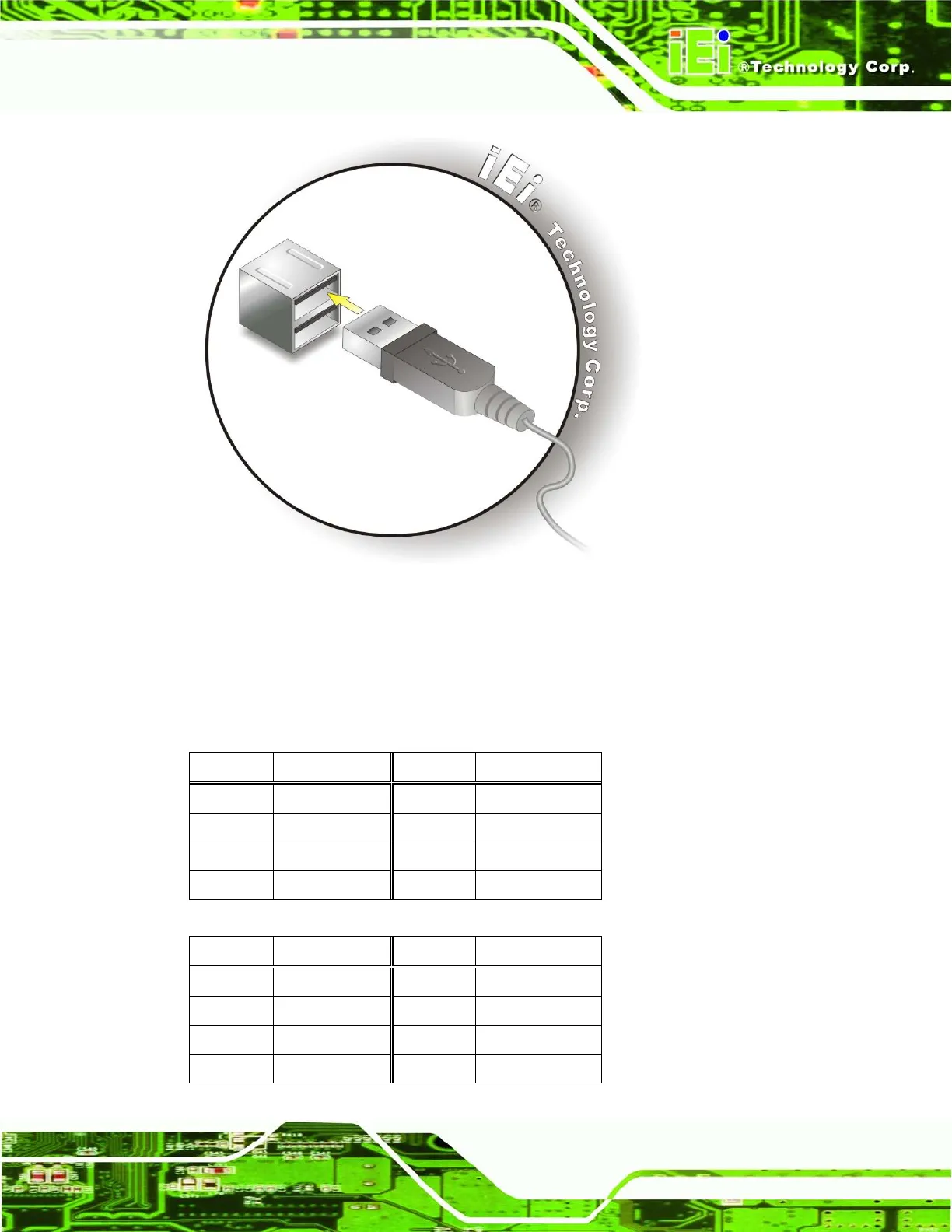
Figure 3-33: USB Device Connection
Step 3: Insert the device connector. Once aligned, gently insert the USB device
connector into the on-board connector.
The pinouts of the USB ports are shown below.
Pin Description Pin Description
1 +5V 5 +5V
2 USB_PN0 6 USB_PN1
3 USB_PP0 7 USB_PP1
4 GND 8 GND
Table 3-8: USB Port Pinouts (USB 2.0)
Pin Description Pin Description
1 +5V 10 +5V
2 USB2P0_N 11 USB2P1_N
3 USB2P0_P 12 USB2P1_P
4 GND 13 GND


