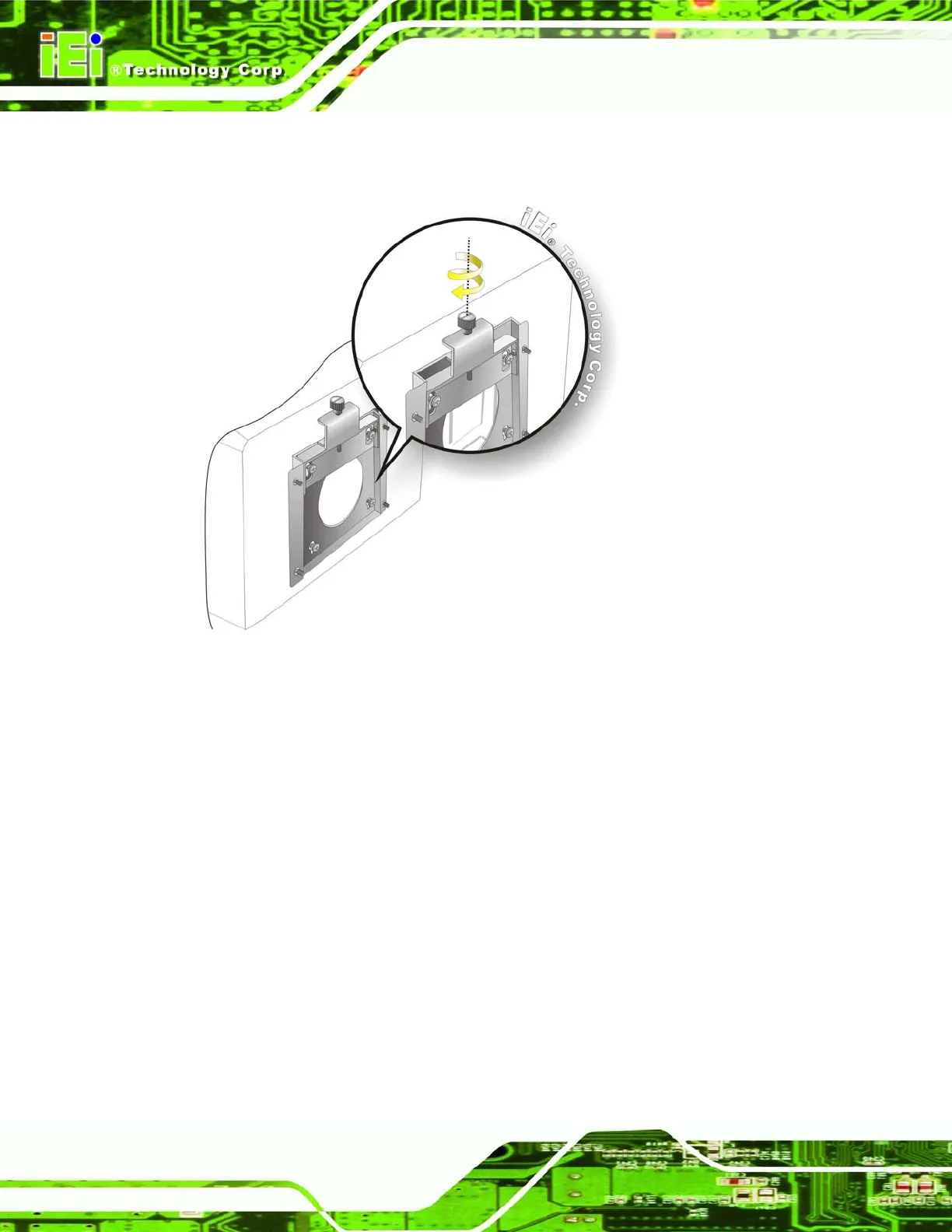
Step 9: Secure the panel PC by fastening the retention screw of the wall-mounting
bracket. (Figure 3-13).
Figure 3-13: Secure the Panel PC
3.7 Bottom Panel Connectors
The bottom panel of the UPC-V315-QM77 contains I/O connectors, switches and a reset
button. These connectors are protected by an I/O cover. Detailed descriptions of the
connectors can be found in the subsections below.
3.7.1 External Peripheral Device Connection
To install external peripheral devices to the UPC-V315-QM77, please follow the steps
below.
Step 1: Remove the I/O cover by removing the ten retention screws as shown in Figure
3-14.


