ENGLISH
33
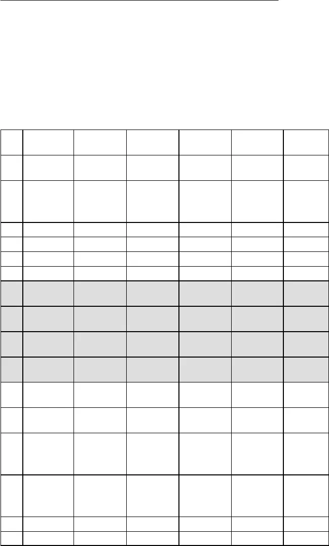
APPENDIX: NETWORK INTERFACE PIN MAP
The U4S and U4D receivers both have a 25–pin network interface located on the
rear panel. The interface allows future monitoring and control of all receiver func-
tions, including audio level, RF level, and “A/B” diversity indication, from a remote
location via an interface device. The table below identifies the signal output by each
pin on the connector. Contact you Shure dealer for addition information.
NOTE: Using any of the pins in the shaded area could result in system mal-
function or damage to your receiver.
Pin Receiver 1
(Left)
Receiver 2
(Right)
Connection Connection
Type
Impedance Voltage
Range
1 Ground Ground Not
Applicable
0 V
2 Audio
Meter
Analog Output 1.2 kΩ 0–2 V
Typical
0–5 V Ma-
ximum
3 RF Level B Analog Output 2.5 kΩ 1–4 V
4 RF Level A Analog Output 2.5 kΩ 1–4 V
5 Diversity B Analog Output 2 kΩ 1–4 V
6 Diversity A Analog Output 2 kΩ 1–4 V
7 Network In-
terrupt
Digital Input Not
Applicable
1–4 V
8 Network In-
terrupt
Digital Output/Busy Not
Applicable
1–4 V
9 Serial Data
Output
Digital Output Not
Applicable
1–4 V
10 Serial Data
Input
Digital Input Not
Applicable
1–4 V
11 5V Not
Applicable
5 V
12 5V Not
Applicable
5 V
13 5V
(indicates
unit is dual
channel)
Not
Applicable
1–4 V
14 Audio
Meter
Analog Output 1.2 kΩ 0–2 V
Typical
0–5 V Ma-
ximum
15 RF Level B Analog Output 2.5 kΩ 1–4 V
16 RF Level A Analog Output 2.5 kΩ 1–4 V


