Page 2 Sensor Mounting Arm
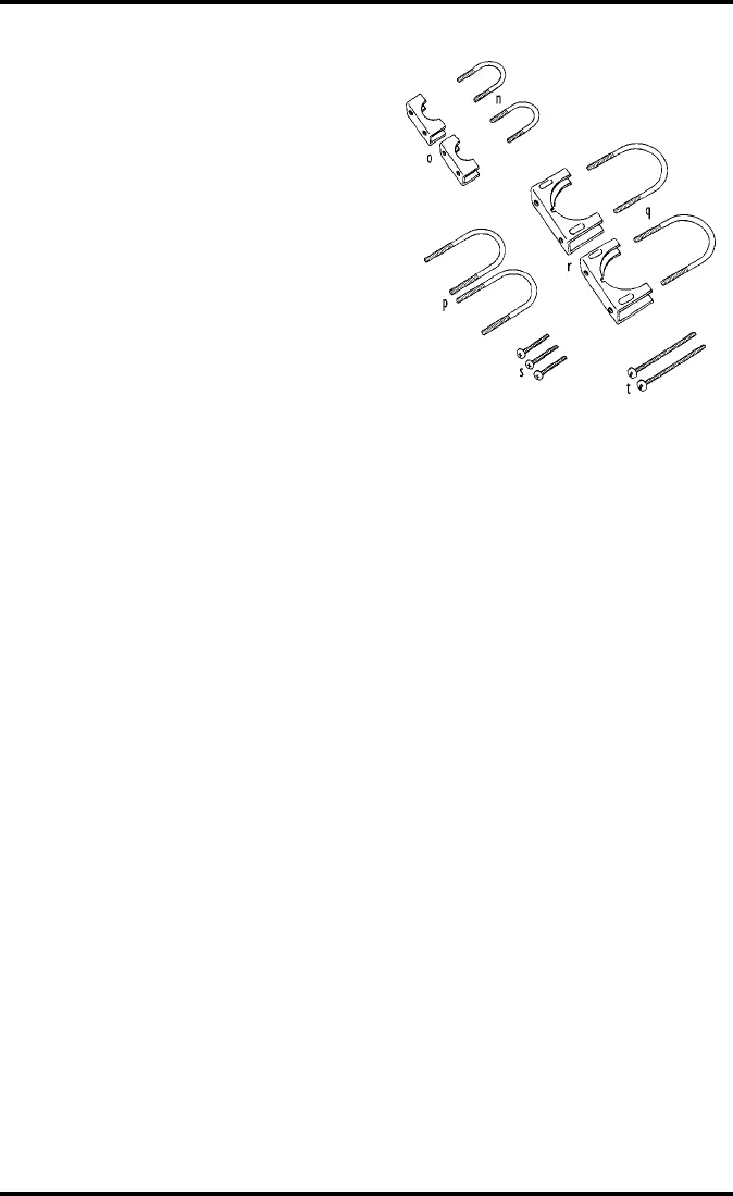
n.
Two 1/2” U-Bolts (for
anemometer arm)
o.
Two 1/2” Saddles
p.
Two 1-1/2” U-Bolts (for
pipe with outside diameter
between 1” and 1-1/4”
(25 mm and 31 mm)
q.
Two 2-1/4” U-Bolts (for
pipe with outside diameter
between 1-1/2” and 2-3/8”
(38 mm and 60 mm)
r.
Two 2-1/4” Saddles
s.
Three #8-32 x 3/4”
(19 mm) Screws
t.
Two #8-32 x 2 -1/2”
(64 mm) Screws
T
OOLS
AND
M
ATERIALS
N
EEDED
In addition to the components listed above, you will need some of the follow-
ing tools and materials. Please be sure you have everything you need before
beginning the installation.
✦
Medium Phillips Screwdriver
✦
Wrench or Pliers
✦
11/32” (9 mm) Nut Driver or Socket Wrench
If mounting the anemometer on the same side as the Radiation Shield.
A
SSEMBLING
THE
S
ENSOR
M
OUNTING
A
RM
The assembly of the sensor arm involves attaching the mounting bracket and
then attaching all desired sensors. Instructions for attaching sensors (other than
the anemometer) to the Sensor Mounting Arm are contained in the manual for
that sensor or for the accessory which allows that sensor to be attached (such as
the Radiation Shield or the Rain Collector Shelf). The Sensor Mounting Arm
includes provisions for attaching the following sensors:
✦
Anemometer
✦
External Temperature Sensor, External Temperature/Humidity Sensor, or Stainless
Steel Temperature Probe (with Radiation Shield or Solar-Fan-Aspirated Radiation
Shield)
✦
Rain Collector (with Rain Collector Shelf)
✦
UV Sensor (with or without Tilting Mechanism)
✦
Solar Radiation Sensor (with or without Tilting Mechanism)


