Component Testing Information
WARNING
To avoid risk of electrical shock, personal injury, or death, disconnect power to washer before servicing, unless
testing requires it.
RT3100016 Rev. 0 November 20002
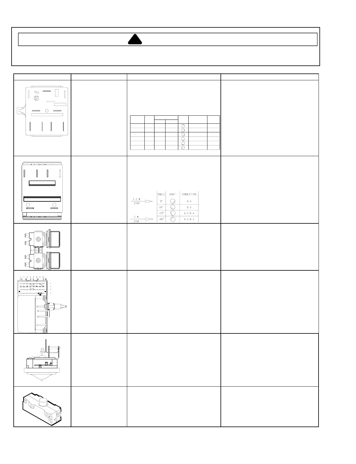
Illustration Component Test Procedure Results
40107102
2
B
1
3
ACD
Temperature switch Disconnect wires from component to
properly measure the resistance of the
component.
Place switch in the following positions
and measure across the terminals
below:
POSITION
2 45°
WARM
WARM
WARM
COLD
5 180°
6 225°
4
3
135°
90°
WARM
COLD
COLD
COLD
COLD
COLD
WASH RINSE
ANGLE
10°
TEMPERATURE
HOT
COLD
NORMAL
NORMAL
NORMAL
NORMAL
B-1,C-1
B-1,C-2,D-3
A-1,B-2
B-1
A-1,B-1
REG.
REG.
A-1
CONNECTIONSHAFT MODE
>1
Ω
>1
Ω
>1
Ω
>1
Ω
>1
Ω
>1
Ω
40108501
1
2
3
4
A
B
ARK-LES
Speed switch Disconnect wires from component to
properly measure the resistance of the
component.
Place switch in the following positions
and measure across the terminals
shown below:
>1
Ω
>1
Ω
>1
Ω
>1
Ω
40107001 Mixing valve Measure resistance of terminals on
each valve.
Resistance across each valve.
Approximately 1000
Ω
±
10%
40107302 Timer Verify input and output voltage is
present.
Verify wiring is correctly connected to
the timer.
See timing sequence chart for functional
description of the component.
40055101
1
2
3
Pressure switch Do not disconnect the pressure hose
from pressure switch to perform
measurements.
Measure resistance across the
following terminals on the pressure
switch:
Terminal 1 to 2
Terminal 1 to 3
Refer to wiring diagram/schematic for
correct contacts.
Air pressure that actuates switch is
determined by the water level of the
tub.
Continuity (no pressure)
Continuity (pressure)
40035001
Lid switch
−
SPST
Disconnect wire terminals from switch.
Test terminals with switch closed.
Test terminals with switch open.
Continuity >1
Ω
Infinite 1 M
Ω


