PAGE 17
FOR SERVICE TECHNICIAN’S USE ONLY
DO NOT REMOVE OR DESTROY
If the resistance is within the range shown
in the table, go to step 6.
If the resistance is infinite or close to zero,
replace the temperature thermistor assembly.
NOTE: Most thermistor errors are a result
of the resistor being out of range. If the
temperature thermistor malfunctions, the
washer will default to pre-programmed
wash settings.
6. If the thermistor is good, replace main
control and calibrate washer. Perform Automatic
Test to verify repair.
TEST #6: Water Level
This test checks the water level sensing
components. Depending on the model, the
washer will have either an on-board pressure
transducer or a separate pressure switch.
NOTE: Usually, if the pressure transducer or
pressure switch malfunctions, the washer will
generate a long fill, or long drain error.
1. Check the functionality of the pressure
transducer or pressure switch by running a
small load cycle. The valves should turn off
automatically after sensing the correct water level
in the tub. The following steps assume that this
step was unsuccessful.
2. Drain the tub until all water has been removed.
3. Unplug washer or disconnect power.
4. Remove console to access controls.
5. Check hose connection between the
pressure transducer or switch and the pressure
dome attached to the tub.
6. Check to ensure hose is routed correctly in
the lower cabinet and not pinched or crimped
by the back panel.
7. Verify there is no water, suds, or debris in
the hose or dome. Disconnect hose from main
control or pressure switch and blow into hose
to clear water, suds, or debris.
8. Check hose for leaks. Replace if needed.
9. If the preceding steps did not correct the
problem, go to step 10 if troubleshooting a
pressure switch, or step 11 if troubleshooting
an onboard pressure transducer.
10. Pressure Switch Only:
a. Remove the pressure hose from the switch.
b. Place the leads of an ohmmeter across
connector J4, pins 1 & 3 of the main control.
Blow into the pressure switch inlet. The
pressure switch contact should close and
show continuity.
If there is no continuity, check the harness
and connections between the pressure
switch and J4 on the main control. If OK,
replace the pressure switch.
If there is continuity, reconnect hose to
pressure switch and continue to step 11.
11. Replace the main control and calibrate
washer. Perform Automatic Test to verify repair.
TEST #7: Drain Pump
Perform the following checks if washer does
not drain.
NOTE: Refer to Figure 6, “Drain Pump Strip
Circuit” for tests and measurements.
IMPORTANT: Drain water from tub before
accessing bottom of washer.
1. Check for obstructions in the usual areas.
Clean and then perform step 2.
Approx. Resistance
F° C° (K
)
32 0 163
41 5 127
50 10 100
59 15 79
68 20 62
77 25 50
86 30 40
95 35 33
104 40 27
1134
2
122 50 18
131 55 15
140 60 12
149 65 10
A
rox. Tem
erature
THERMISTOR RESISTANCE
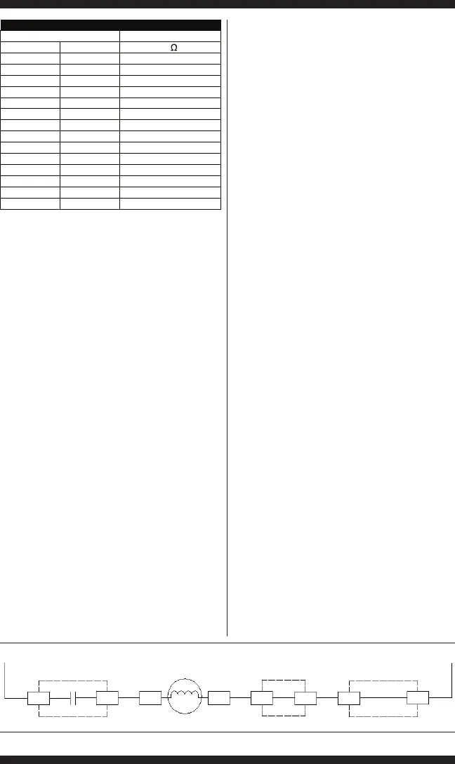
Figure 6 - Drain Pump Strip Circuit
Main Control Shifter Assy
L1
Main Control
N
J16-3J7-1 J16-2
Pin 1
Pin 1
Pin 2
Pin 2 J7-3
K7
120VAC
Motor
Motor Resistance 14 to 25 ohms
Drain Pump Motor Relay
Drain Pump Motor


