PAGE 15
FOR SERVICE TECHNICIAN’S USE ONLY
DO NOT REMOVE OR DESTROY
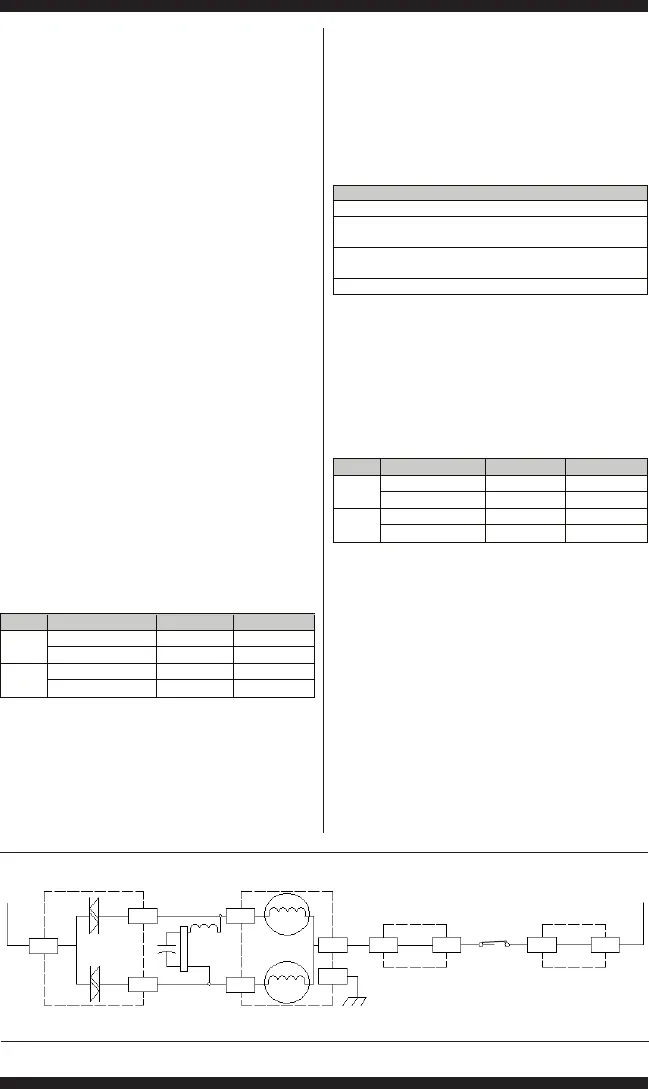
Figure 5 - PSC Motor Strip Circuit (shown in ON position)
Main Control
CW TRIAC
Main Control Main Control
CCW TRIAC
J15-3
J15-4J16-5
Pin 9
Pin 1
Pin 6
Pin 3
J16-7
J16-6
J7-3
J7-1
PSC Motor
Run
Cap
CW Winding*
CCW Winding*
Lock Switch
N
L1
* 1/3 HP Motor – Each Winding 3.5 to 6 ohms/ * 1/4 HP Motor – Each Winding 5 to 9.5 ohms
1
3
If visual checks pass, go to step 6.
If connectors are not inserted properly,
reconnect J2 and J16 and repeat step 1.
6. Plug in washer or reconnect power. Run the
Gentle Agitation test under Manual Test Mode
on page 9.
7. With a voltmeter set to AC, connect black
probe to J16-5 (N) and red probe to J16-6
(CW Winding).
If 120VAC is cycling ON during CW rotation,
go to step 8.
If 120VAC is not present, go to Test #1:
Main Control, page 12.
8. With a voltmeter set to AC, connect black probe
to J16-5 (N), red probe to J16-7 (CCW Winding).
If 120VAC is cycling ON during CCW
rotation, go to step 9.
If 120VAC is not present, go to Test #1:
Main Control, page 12.
9. Unplug washer or disconnect power.
10. Remove connector J16 from main control.
With an ohmmeter, check resistance of motor
windings across the following J16 connector
pinouts:
NOTE: If the console has a cycle selector knob
and 4 rotary switches, the motor size is 1/3 HP.
If values are open or out of range, go to step 11.
If values are correct, go to step 15.
11. Tilt washer back to access drive system.
12. Visually check the mounting bracket and
electrical connections to the motor and shifter.
If visual check passes, go to step 13.
If connections are loose, reconnect the
electrical connections, reassemble motor
cover, and repeat step 1.
13. With an ohmmeter, check the harness
for continuity between the main control, motor,
and run capacitor using the following test points.
If there is continuity, go to step 14.
If there is no continuity, replace the lower
machine harness and repeat step 1.
14. With an ohmmeter, check resistance of motor
windings at the following motor connections.
NOTE: If the console has a cycle selector knob
and 4 rotary switches, the motor size is 1/3 HP.
If values are open or out of range, replace
motor.
If values are correct, go to step 15.
15. Test Motor Run Capacitor. NOTE: A faulty
capacitor may cause the motor to “hum”, not
start, or turn slowly.
a. Discharge the capacitor by touching the leads
of a 20,000 Ω resistor to the two terminals.
b. Disconnect the wires from the capacitor
terminals.
c. With an ohmmeter, measure across the
terminals and note reading.
If a steady increase in resistance is noted,
continue to step 16.
CW Winding J16, 5 & 6
CCW Winding J16, 5 & 7
1/4 HP
5 to 9.5 Ω
5 to 9.5 Ω
CW Winding J16, 5 & 6
CCW Winding J16, 5 & 7
1/3 HP
3.5 to 6 Ω
3.5 to 6 Ω
Motor Harness Check
Motor Connector Pin-1 to Chassis Ground
Motor Connector Pin-3 to Main Control J16-7
Motor Connector Pin-3 to Run Capacitor Pin-3
Motor Connector Pin-6 to Main Control J16-6
Motor Connector Pin-6 to Run Capacitor Pin-1
Motor Connector Pin-9 to Main Control J16-5
Motor Winding Motor Pinout
CW Winding Pins 6 & 9
CCW Winding Pins 3 & 9
1/4 HP
5 to 9.5 Ω
5 to 9.5 Ω
CW Winding Pins 6 & 9
CCW Winding Pins 3 & 9
1/3 HP
3.5 to 6 Ω
3.5 to 6 Ω
Inductive
Wire Loop


