Chapter 2 - Installation
MTASR
15
Cabling your RouteFinder
Before you attach the cables to your RouteFinder, you have to determine two things: if the WAN ports
are to be used with a V.35 interface and if additional RAM needs to be added. Both of these
considerations require that the PC board be removed from its enclosure before you connect your
external cables.
If the V.35 interface is going to be used, perform the procedure in Table 2-2 to move the shunt(s) from
their default (RS232C/D) position(s) to the V.35 position(s).
If additional RAM is needed, perform the procedure in Table 2-3 before you connect your cables.
To connect the cables to your RouteFinder, perform the cabling procedure in Table 2-1.
Table 2-1. Cabling Procedure
Step Procedure
1 If one or more links need to be changed to a V.35 interface, perform the procedure in Table 2-2.
2 If additional RAM is needed, perform the procedure in Table 2-3.
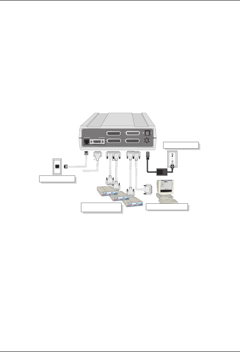
Ethernet Connection
T1 CSU/DSU or Comparable
Link Device
Power Connection
Command Port Connection
10BASE T
ETHERNET
POWER
COMMAND PORT
LINK 1 RS232/V.35
LINK 3 RS232/V.35
LINK 2 RS232/V.35
AUI
Figure 2-2. Back Panel Connections
3 Connect the RouteFinder to your PC using a standard RS232 cable with DB25 connectors on both
ends. Plug one end of the cable into the Command Port on the RouteFinder. Plug the other end into
the PC's serial port. See Figure 2-2.
4 To make the network connection, connect either an RJ-45 (UTP) cable to the 10 BASET connector, or
the male connector for the 10 BASE5 to the AUI connector. Connect the other end of the cable to
your LAN.
5 Connect an RS232C/D or V.35 interface cable to the LINK 1 RS232/V.35 connector as shown in
Figure 2-2. Connect the other end of the cable to the mating connector on the external link device.
Connect similar cables between the LINK 2 and LINK 3 connectors to external link devices.
6 Connect one end of the power supply to a live AC outlet, then connect the other end to the POWER
connector on the RouteFinder as shown in Figure 2-2. The power connector is a 6-pin circular DIN
connector.
7 Turn on power to the RouteFinder by setting the ON/OFF switch on the back panel to the ON
position.
At this time your RouteFinder is completely cabled and powered On. Proceed to the next section to
load the RouteFinder software.


