Table 1 — Weight Distribution (ib)
UM!T
30( )--
APPROX
OPERWT
HK
HL
HK HL A I B C
D A B
C
D
015
1637
1016
142j 201 755
539
266 266
242
242
020
1787
1136
182| 240
790 575 296 296 272
272
025
1980
1310 3031 205
592 880
367
285
285 373
030
1985
1334
3031 205
592 885 377
290 290
377
Location of mounting holes:
WATER
i
INLET
1
PLAN VIEW
i
END
FRONT
SClF-IlOCKINö
0OLT
—
J
_
SNOb&ER Ft.ANo>--0
WASHER
NEOPHENE
SNUSSKR
'COMPRESSOR FOOT
ISfL A'lON S-RING
Fig. 2 — Compressor Mounting
To ensure safe moving, unit should remain on
shipping skid until final placement. If unit is moved
on rollers, use minimum of 3. Unit can also be
dragged into final position (must be on skid).
When rolling or dragging, apply force to the skid,
not the unit. Use care to avoid damage to piping and
control box.
PLACEMENT
When unit is in final position, remove skid, level
unit with a spirit level and bolt to floor or pad.
These units are not suitable for unprotected
outdoor use.
Carrier recommends that these units be located
in the basement or on the ground floor. However,
if it is necessary to locate unit on an upper floor,
be sure the structure has been designed to support
the weight. If necessary, add structural support to
floor. Also, be sure surface for installation is level.
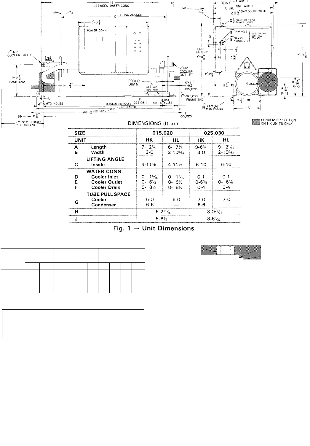
Refer to Fig. I for space requirements and Table 1
for weight distribution.
1090


