3
Motherboard Pin Layout
Connecting the Audio Ports (AC’ 97 and HDA)
The case has both an Intel standard 10-pin AC’ 97 connector and an Intel 10-pin
HDA (High Definition Audio) connector. You can connect either the AC’ 97 or the
HDA connector to your motherboard depending on the spec of the motherboard. If
your motherboard supports Intel’s standard onboard AC’ 97 audio connector, plug
the AC’ 97 connector directly onto the board. If your motherboard supports Intel’s
High Definition Audio, plug HDA onto the board. See instruction below:
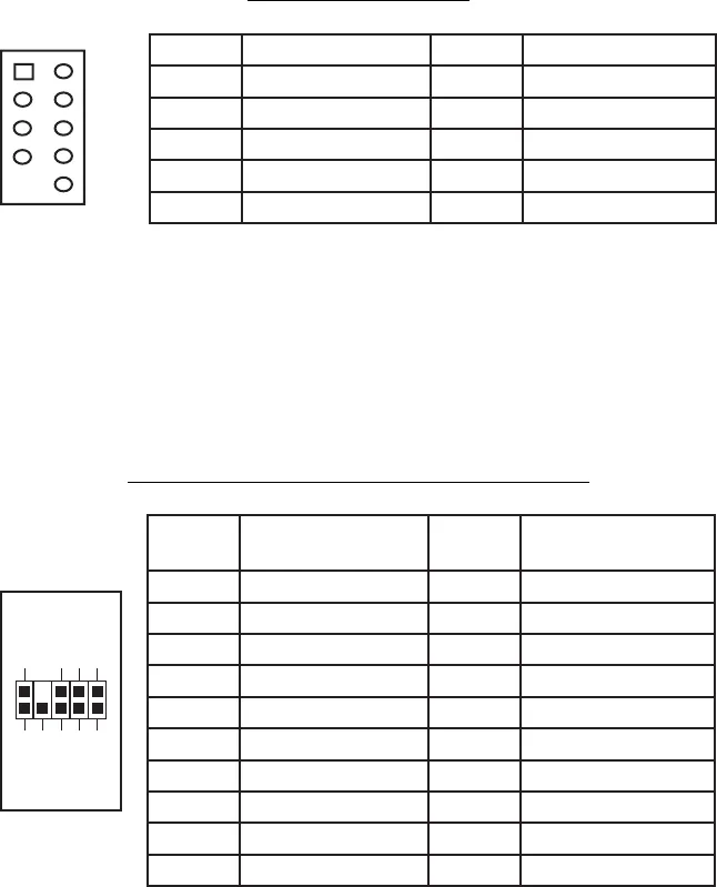
Pin Assignment for Audio Ports (HDA and AC’97)
Locate the internal audio connectors from your motherboard or sound card. Consult
your motherboard or sound card manual for the pin-out positions.
Connecting the eSATA Port
You will find a SATA connector on a cable attached to the front ports. This
internal SATA connector is designed to connect to a standard SATA connector
on your motherboard.
Pin Signal Names Pin Signal Names
1
USB Power 1
2
USB Power 2
3
Negative Signal 1
4
Negative Signal 2
5
Positive Signal 1
6
Positive Signal 2
7
Ground 1
8
Ground 2
9
Key (No Connection)
10
Empty Pin
12
10
9
Pin Signal Names
(HDA)
Pin Signal Names
(AC’97)
1 MIC2 L 1 MIC In
2 AGND 2 GND
3 MIC2 R 3 MIC Power
4 AVCC 4 NC
5 FRO-R 5 Line Out (R)
6 MIC2_JD 6 Line Out (R)
7 F_IO_SEN 7 NC
8 Key (no pin) 8 Key (no pin)
9 FRO-L 9 Line Out (L)
10 LINE2_JD 10 Line Out (L)
1
2
3579
46
10


