2
2. Make sure you have the appropriate I/O panel for the motherboard. If the
panel provided is not suitable for the motherboard, please contact the
motherboard manufacturer for the correct I/O panel.
3. Remove the cross bar on the motherboard chamber.
4. Line up the motherboard with the raised mounting holes. There are three
special brass standoffs pre-installed on the motherboard tray. Two of them
are threaded and one without threads.
5. Remove the motherboard by lifting it up.
6. Remove any of the standoffs that are not needed.
7. Place the motherboard back in the case and line it up with the standoffs and
motherboard tray holes.
8. Attach the motherboard to the threaded brass standoffs with the special nuts
that come in your tool bag.
Note: You do not need to fasten the unthreaded brass standoff.
9. Fasten the motherboard to the raised mounting holes with the provided
Philips-head screws. The motherboard is now installed.
Connecting the Power and LED
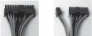
If the motherboard has a 20-pin power receptacle, detach the 4-pin attachment on
the 24-pin power connector, see pictures 1 and 2. Before you connect the power
supply to any of the devices, please consult the appropriate user manuals for the
motherboard and other peripherals.
1. Connect the 24-pin Main Power Connector and
the 4-pin or 8-pin 12V connector to the motherboard
as needed. If the motherboard uses a 20-pin
connector, detach the 4-pin attachment on the
24-pin power connector (see pictures 1 and 2).
Note: the detachable 4-pin section cannot be used
in place of a 4-pin +12V connector.
2. Connect the Reset switch (labeled RESET SW) to
the motherboard at the RST connector. Polarity
(positive and negative) does not matter for switches.
3. The Power Switch (labeled POWER SW) connects to the PWR connector on
the motherboard.
4. The Power LED (labeled POWER LED) connector is located behind the Reset
connector. For LEDs, colored wires are positive (+). White or black wires are
negative (–). If the LED does not light up when the system is powered on, try
reversing the connection. For more info on connecting LEDs to your motherboard,
see your motherboard manual.
5. The Hard Drive LED (labeled HDD LED) connects to the hard drive activity header.
Connecting the USB Ports
You will find a single 10-pin connector on a cable attached to the front USB ports.
This Intel standard connector is keyed so that it can’t be accidentally reversed as
long as it is connected to a proper Intel standard motherboard header. Connect the
10-pin connector to the motherboard headers so that the blocked pin fits over the
missing header pin.
Note: Please check the motherboard manual for the USB header pin layout and
make sure it matches the table below. If it does not match this Intel® standard,
please visit Antec’s web store at http://www.antec.com/StoreFront.bok and
search for part number 30095 to order a USB Internal Adapter Cable. This adapter
will allow you to connect the front USB to your motherboard on a pin-by-pin basis.
Picture 1 Picture 2
For 24-pin
motherboards
For 20-pin
motherboards


