Assembly (continued)
Fig.3-7
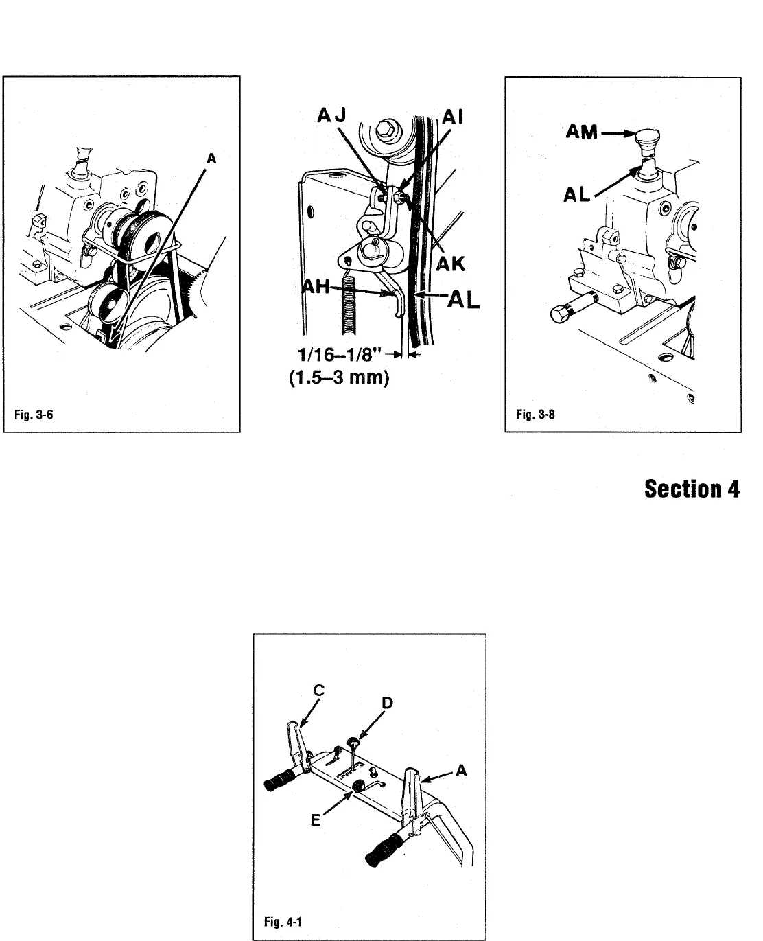
Controls
Wheel Drive Control Lever
Wheel drive control lever (C, Fig. 4-1) is
iocated on top of left-hand handlebar tube
in front of hand grip. Push down to
engage wheel drive. Release to disengage.
Auger Drive Control Lever
Auger drive control lever (A, Fig. 4-1) is
located on top of right-hand handlebar
tube in front of hand grip. Push down to
engage auger (auger will rotate). Release
lever to disengage.
Gear Shift Lever
Located just left of center on control panel
(D, Fig. 4-1). Use to select one of five
forward gears or one of two reverse gears.
Gear shift lever does not control auger
speed. Select a gear by moving lever left,
then forward or rearward. Align lever with
notch for desired gear. While operating
unit, release wheel drive control lever and
come to a complete stop if moving. Select
desired notch and re-engage wheel drive
control lever.
When familiarizing yourself with gears or
when operating near obstacles, use lower
gears (first or second gear).
Discharge Chute Crank & Cap
Located slightly to right at center of
control panel (E, Fig. 4-1). Turning
discharge chute control crank clockwise
turns discharge chute left. Approximately
10 turns of crank are required to move
discharge chute from full left to full right.


