Assembly (continued)
Wiring Harness Instailation
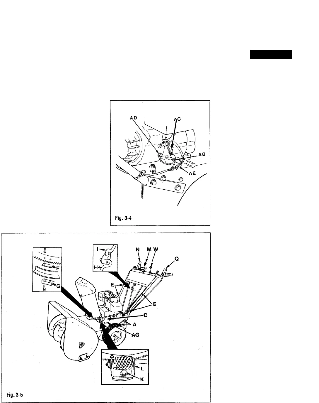
1. Connect lead wire (AB, Fig. 3-4) to
engine wiring harness connector. Plug lead
wire into connector receptacle containing
yellow wire (AC).
2. Connect eye terminal to screw (AD)
on engine shroud. Plug connector (AE)
into engine plug.
3. Secure wires to handlebars with tie
straps (E, Fig. 3-5).
Brake Arm Adjustment
1. Remove bolts securing belt cover
(AG. Fig. 3-5). Lift belt cover (C) up and off
unit.
2. Check brake arm adjustment:
A. Fully depress and hold auger
drive handlebar control lever (N). A second
person may need to hold handle down.
B. Look down through pulleys and
belts at front of engine (A, Fig. 3-6). Check
gap between brake arm (AH, Fig. 3-7) and
belt (AL). Gap should measure between
1/16" and 1/8" (1.5-3 mm).
C. To adjust gap, loosen nut (Al).
Hold set screw (AK) in place with an alien
wrench and turn nut (AJ) until proper
clearance is obtained. Retighten nut (Al).
3. Reinstall belt cover.
Engine Oil
CAUTION
Engine is shipped WITHOUT oil.
DO NOT start engine before adding
correct type and amount of engine oil.
See engine owner's manual.
1. Unscrew oil fill cap (AM, Fig. 3-8) and
place aside. Insert a clean funnel into oil filler
tube (AL).
2. Slowly pour oil of the correct type
(see engine owner's manual) through
funnel and into oil filler tube. Engine holds
approximately 26 ounces. Fill to FULL
mark on dipstick.
NOTE: DO NOT overfill. While adding
oil to engine, frequently stop and check
oil level.
Tire Pressure
1. Check tire inflation pressure.
2. To help prevent pulling to one side,
inflate both tires evenly (8 to 12 psi).
Auger Gear Case Oil
Check auger gear case oil level. See
"Lubrication" on page 16 for instructions.


