Rev: 10102000
3
Chapter 2 Hardware Installation
2.1. Panel Layout
2.1.1. Front Panel
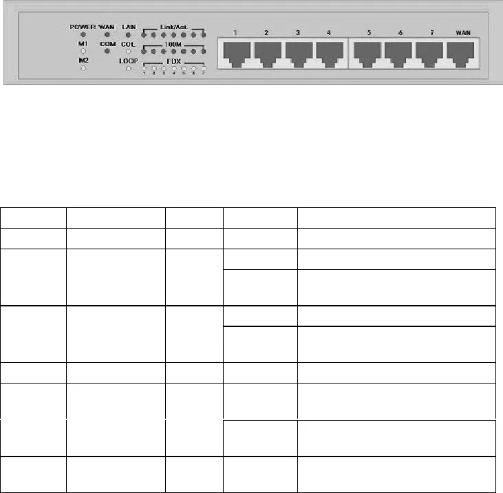
All LED indicators and RJ-45 connectors are allocated to the front panel.
Figure 2-1 Front Panel
WAN: the port where you will connect your cable (or DSL) modem or Ethernet router.
Port 1-7: the ports where you will connect networked computers and other devices.
LED indicators:
LED’s Function Color Status Description
POWER Power indication Green On Power is being applied to DI-707.
On The WAN port is linked
WAN
WAN port
activity
Green
Blinking
The WAN port is sending or
receiving data
On The LAN port is linked
LAN
LAN port
activity
Green
Blinking
The LAN port is sending or
receiving data
M1 System status 1 Orange Blinking DI-707 is functioning properly
On
DI-707 is working for some
service
M2 System status 2 Orange
Blinking
DI-707 is being configured or
upgraded. Don’t turn it off !
COM
Serial port
activity
Green Blinking
Data transfer is in progress
through COM port


