G-9420
PAGE 1
January 2001
INSTRUCTION INFORMATION
PROGRAMMABLE AUDIO LINE SWITCH
G-9420
GENERAL DESCRIPTION
The Programmable Audio Line Switch
(PALS), model G-9420, allows the customer
to access devices within the substation
from a single telephone communications
line with only one call to the station. Once
the G-9420 has answered, a window of time
opens to allow direction of the call to one
of the eight ports. If the call is not directed
using DTMF tones, the G-9420 defaults to
and rings port 1 after approximately 10 sec-
onds. When communication to a port is complete, the user may redirect the call to another port once
that device has gone on-hook. Port 1 is typically used for the handset in the station. A station
emergency requiring use of this handset disconnects all other ports when port 1, or the handset, goes
off-hook.
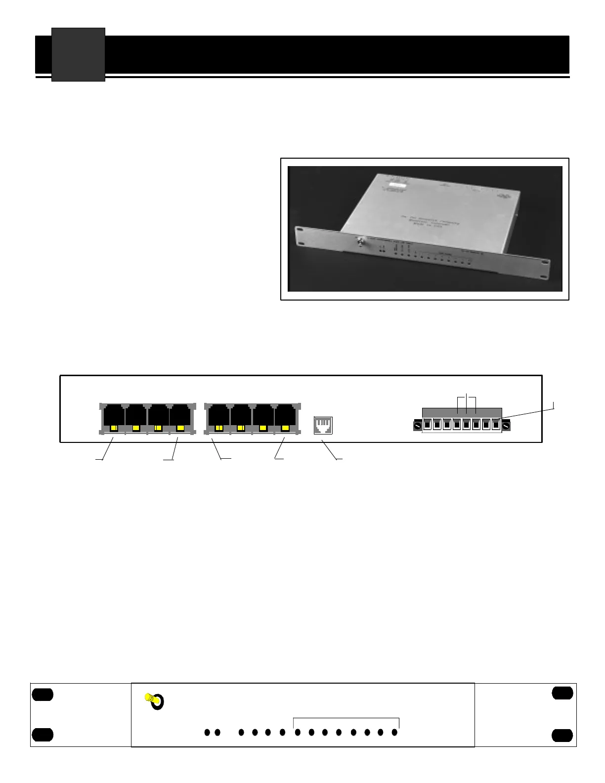
PORT 1
PORT 4 PORT 5 PORT 8 LINE IN
24
57
6
8
13
TB1
+
–
G
ALARM
VDC
IN
àß
+
–
5V
FIGURE 1
INSTALLATION
TELEPHONE CONNECTIONS:
All telephone lines are terminated on a 2-
wire, RJ-11 connector. If a 4-wire plug is
used, the middle pair of contacts, usu-
ally red and green wires, is used by the
PALS for communication. The LINE IN
jack is for connecting the PALS to the line
entering the building or station from the
telephone company. The other 8 RJ-11
jacks connect the PALS to the devices in
the station. Port 1 is the recommended
port for the local station telephone since
it may be programmed to interrupt all
other ports.
POWER CONNECTIONS:
The top of the case is labeled to show what
system voltage the PALS is configured to
operate on. Note that the 125Vdc unit
operates on both 125Vdc and 115Vac.
The power input is wired with the "+" or
"L" of ac into the "+" input on TB1, termi-
nal 1. The "-" or "N" of ac connects to the
"-" input at TB1, terminal 2. The chassis
ground connection at TB1, terminal 3, is
very important for the protective circuitry
of the PALS; therefore, connect it to a very
good ground.
AUXILIARY CONNECTIONS:
The G-9420 is provided with an alarm
relay output at TB1, terminals 4, 5 and
6. This relay contact toggles when the
power is turned off on the unit or the
microcontroller fails to run. This relay
follows the green "ON" LED on the front
panel (see Figure 2). When operating
normal, the relay contacts are closed
from terminal 5 to 6 and open when
power is lost.
The G-9420 internal power supply gen-
erates +5Vdc and is made available at
G-9420 PROGRAMMABLE AUDIO LINE SWITCH
ON
O
N
C
.
P
.
D
T
M
F
L
O
C
A
L
R
I
N
G
R
I
N
G
I
N
D
I
C
A
T
I
O
N
O
F
F
H
O
O
K
1
2
543
PORTS AVAILABLE
6 87
Da-Tel Research Co.
FIGURE 2


