G-9420
PAGE 3
January 2001
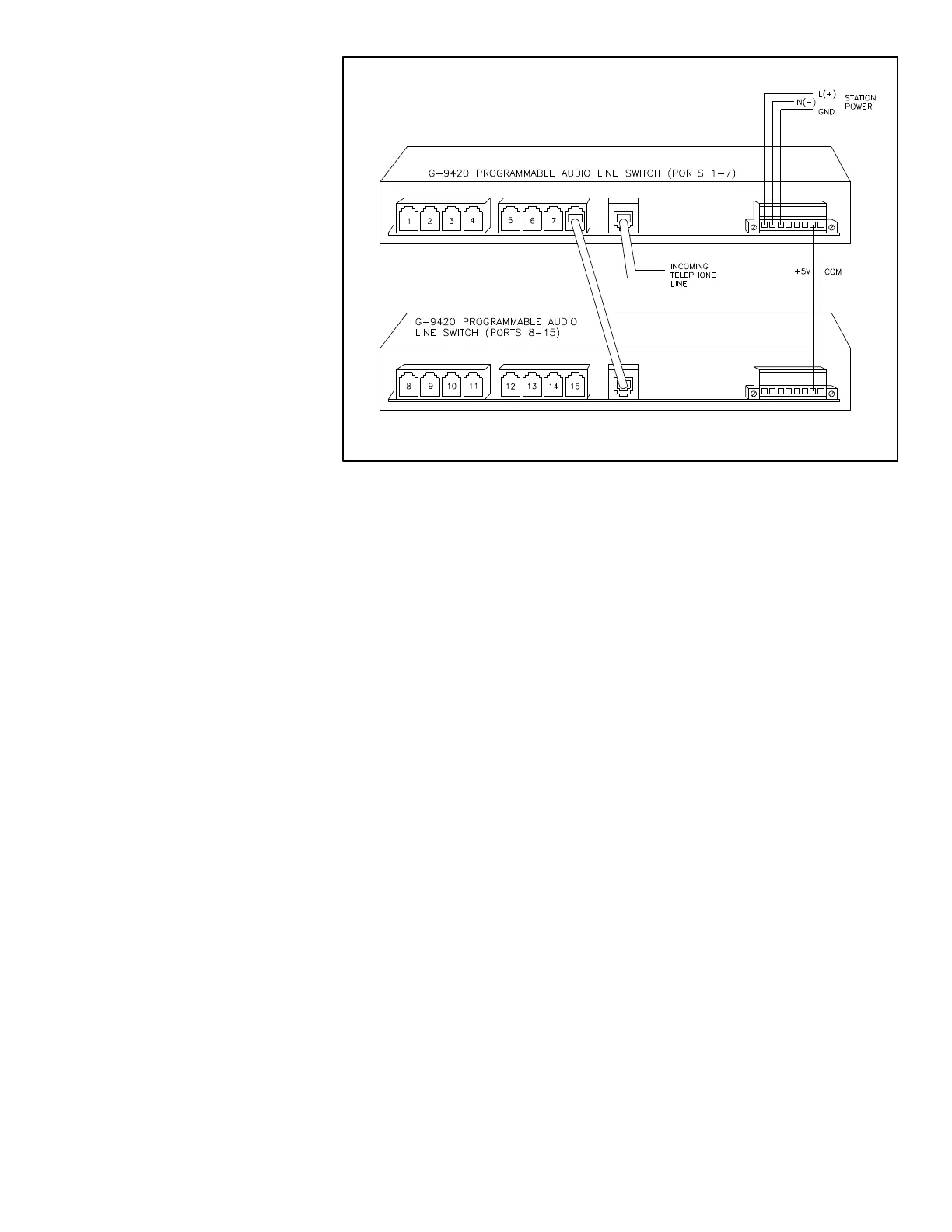
FIGURE 3
TESTING AND
CALIBRATION
GENERAL
The G-9420 Programmable Audio Line
Switch (PALS) allows the user to dial
into a station over a single telephone
line and connect to multiple devices
connected to its ports. This device has
programmable features that also need
checking.
SETUP
Connect the dc input power such that
the positive (+) is on terminal 1 and the
negative (-) is on terminal 2. Connect a
ground to terminal 3, also.
A Teltone Line Simulator (TLS) is
needed to verify that calls are com-
pleted. Connect one port of the TLS to a
touch-tone phone and the other port of
the TLS to the LINE IN on the G-9420.
Multiple phones may be connected to
the ports of the G-9420 to have devices
to call in to.
TEST PROCEDURE
POWER-UP
Apply power and observe that the
green ON LED is lit. The yellow PORTS
AVAILABLE LEDs should also be on.
CALL PROGRESS (CP) TONES AD-
JUSTMENT (Line-In disconnected)
Install J3 on the board this will initate
the internal test tone and adjust the test
tone level at TP3 to TP7(signal ground)
to +3.5 dBm with the front panel trim-
mer labeled C.P., R11.
DUAL TONE MULTPLE
FREQUENCY(DTMF) RECEIVE
LEVEL ADJUSTMENT(Line-In dis-
connected)
Install J3 on the board this will initate
the internal test tone. Adjust the test
tone level at TP2 to TP7 to -9 dBm with
the front panel trimmer labeled DTMF,
R10.
FAX DETECT ADJUSTMENT
Line-In may or may not be connected,
J3 must be out or not installed. Adjust
R46 for 1100Hz at pin 5 or 6 of U26,
then inject an 1100Hz -30dbm signal
between TP1 and TP7 and observe pin
8 of U26 going low (from 5V to 0V)
PORT RINGS (all ports)
With the TLS and handset connected,
check all ports by dialing the G-9420.
Connect another phone to each port
sequentially and redirect the calling
to each port. Check to see that each
corresponding port LED lights. Also,
when the TLS is ringing, the RING
INDICATION LED should light for
each ring of the TLS. Then the OFF
HOOK LED should light when the
G-9420 goes off hook. When a port is
ringing, the LOC RING LED should
light.
PORT ANSWER (all ports)
With the TLS and handset connected,
check that all ports answer by dialing
the G-9420. Connect another phone to
each port sequentially and redirect the
calling to each port. Check to see that
each corresponding port LED lights
and that the path is complete when the
port phone is answered. Depressing
keypad numbers is a good check to see
if the audio path is good.
ROTARY (all ports)
With the TLS and handset connected,
check all ports for rotary service by
ringing the TLS phone from each port
of the G-9420. If each port rings the
TLS phone, rotary option is working.
PRIORITY PORT INTERRUPT
With the TLS and handset connected,
connect a phone to port 1 and another
to port 2. With the priority port option
programmed, dial port 2 of the G-9420
and answer with its phone. Ports 1
and 2 LEDs should be on. Pick up the
port 1 phone and observe that the de-
fault time delay occurs before control is
given to port 1 (port 1 LED lights by
itself). Reprogram the G-9420 to dis-
able priority port interrupt and rerun
the test to verify that port 1 does not
disconnect port 2 (*5720#). Reprogram
to priority port interrupt enabled
(*5721#).
INTERRUPT DELAY OPTION
Set the priority port interrupt delay
code for a longer time, such as 10 sec-
onds (*44100#), and rerun the previous
test to verify the programming of the
delay. When done, reset the delay to
where this accesses port 10 (port 3 of
the second G-9420). The number of
commas between the 8 and 3 is depen-
dent on the connect time between the
two units, 1 is sufficient. The 8 rings
the second G-9420 and the 3 rings the
port of interest.


