G-9420
PAGE 2
January 2001
terminals 7 and 8. This power may be
used for another G-9420 or for 5Vdc mo-
dems such as the G-9615A. Up to 1A may
be used from this supply without con-
cern.
INDICATORS:
The G-9420 PALS provides many indica-
tors to help the user know what is going
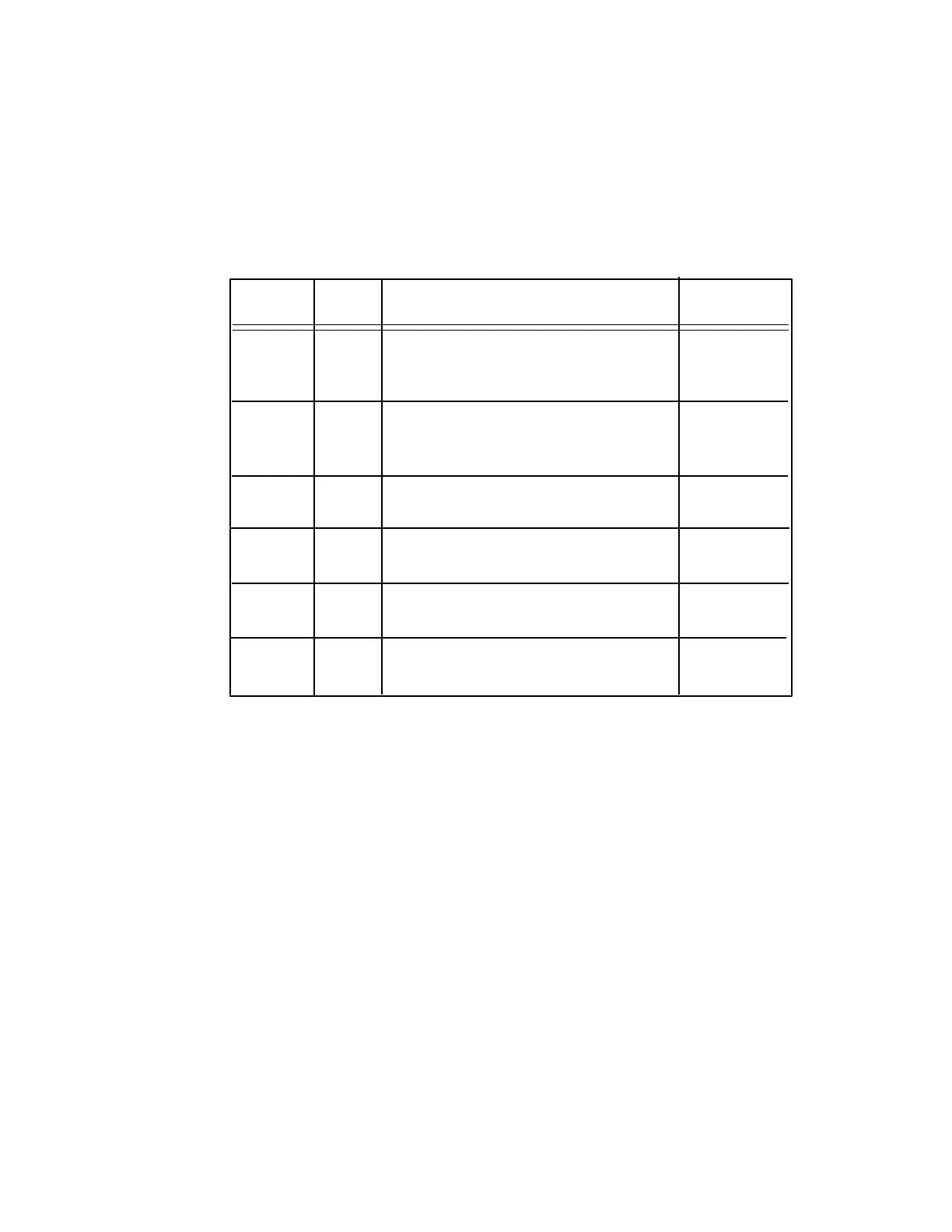
TABLE 1
LED COLOR DESCRIPTION NORMAL
LABEL STATE
RING Red Indicates when an incoming ring signal
Indication is being applied to the G-9420. OFF
OFF Yellow Indicates when the G-9420 has answered OFF, only ON
HOOK and gone off hook. Will go out once port when G-9420
device goes on hook. holds the line.
LOCAL Red Indicates when a port is being rung. OFF
RING
ON Green Indicates when power is on and CPU ON
is running.
PORT 1 Yellow Indicates when port 1 is available or is ON - available
off hook. or off hook.
PORT 2-8 Yellow Indicates when a corresponding port is ON - available
available or off-hook. or off-hook.
on and diagnose any problems (see Table
1).
If port 1 yellow LED flashes on power
up, an error has been detected in the time
clock for the DTMF decoder. If the port 7
yellow LED flashes, the NVRAM
memory space is not available. Note also
that the red RING INDICATION LED is
merely a flash since the G-9420 answers
immediately.
MOUNTING:
The unit may be either 19" rack-mounted
or the cover may be removed and the 4
internal ¼" holes used for panel mount-
ing.
APPLICATION NOTE
FOR USING TWO G-9420 PALS
TO ACCESS UP TO 15 AUDIO PORTS
GENERAL
This application note encompasses
how to apply the Da-Tel G-9420 Pro-
grammable Audio Line Switch to an
application requiring more than 8 ports
but not more than 15.
No special programming of the
G-9420s is required to access the sec-
ond G-9420. The standard, factory con-
figuration was used to test these hard-
ware configurations.
HARDWARE
Figure 3 illustrates a typical applica-
tion of two Da-Tel G-9420s. All that is
required is the addition of devices to
the ports to be accessed by the incom-
ing telephone line.
The G-9420 is connected to the station
battery according to the marking on the
case for polarity. With the two G-9420s
operating adjacent to each other, 5 Vdc
can be derived from the first G-9420 to
power the second G-9420. The switch
on the first G-9420 controls the power
for both units and the second G-9420's
switch is inactive. It is important for
noise reduction to connect the ground
terminal of the G-9420s to a good
ground.
The telephone line into the site should
connect with an RJ-11 termination into
the G-9420 where marked INCOMING
LINE. Port 1 of the G-9420 is typically
a local handset for use by the mainte-
nance personnel. Port 8 is used to make
connection to the second G-9420, how-
ever, any port could be used. Ports 2
through 7 on the first G-9420 and ports
1 through 8 on the second G-9420 are
available for dial-up devices. The dia-
gram shows numbering for a 15 port
setup.
PORT ACCESS
To access a port between 1 and 7 (2 for
example), use the following sequence:
1(303)249-8919,,,2
where the number of commas is depen-
dent on the telephone exchange connect
time; three is a good start. To access a
port between 8 and 15 (10 for example),
use the following sequence:
1(303)249-8919,,,8,3


