Technical data
Dimensions, mm 34 1/4" X 23 1/2" X
23 1/2"
Weight 170 lbs
Spin speed 800/1000 r/min
Rated load 3505 W/240 V
3240 W/230 V
Supply voltage 208-240 V, 60 Hz
single-phase
Heater rating 3265W/240V
3000 W/230 V
Material of drum
and barrel
Stainless steel
Material of
outer casing
Stove-enamelled
hot-dip-galvanised
steel sheet
Mounting
Stationary: four
adjustable rubber-
covered feet
Water suppiy
hose
5 ft pex hose
Supply pressure 0.1-1 MPa
(10-100 N/cm*,
1-10 kp/cm*,
15-146 PSI)
Outlet 5.5 ftof poly-
propene hose,
3/4" internal
diameter
Accessories
The machine is supplied with:
• Operating instructions and
installation instructions.
• Guarantee card.
• Type-approved inlet hose for
connection to water supply.
Optional extras:
• Decor frames
• Edging frame by stacked
machines
• Frame set with pull-out shelf by
stacked machines.
Installation Instructions
Removing the shipping brace
The shipping brace consists of two tubes
which prevent the barrel from moving
around inside the machine during
transport. The tubes are secured to a
cross beam at the back of the machine.
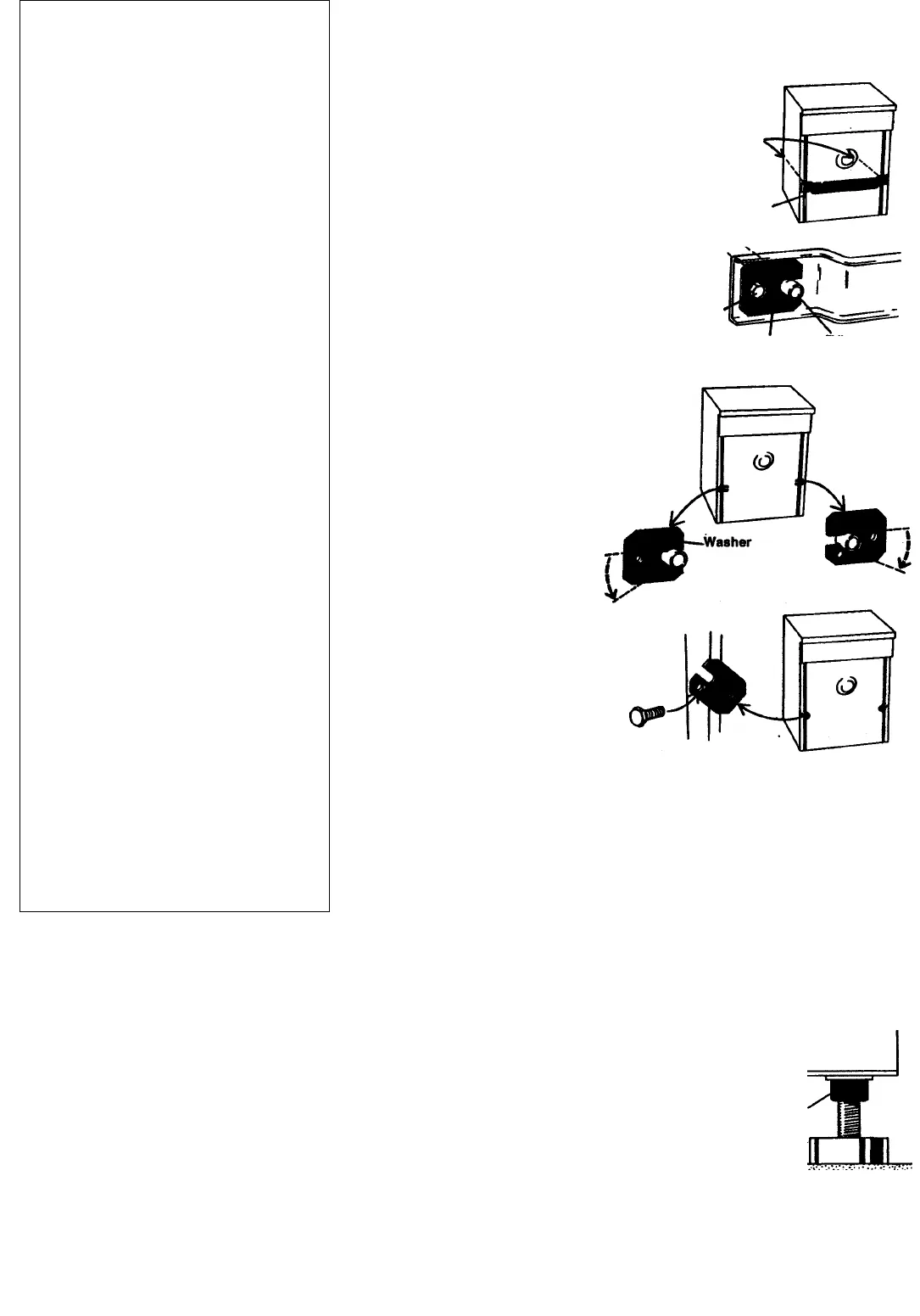
Remove the shipping brace as follows:
1. Remove the bolts and special
washers which retain the beam,
and remove the beam.
Two tubes
inside
the machine
Cross beam
Boit
Washer
Tube
2. Replace the washers on the flattened
part of the tubes. Use them as tools
to turn the tubes through about 45°,
as shown in the drawing, and pull out
the tubes.
3. Turn the washers so that
they cover the holes
where the tubes were
fitted and replace the
bolts.
Save the tubes and cross beam,
which will be needed if the machine
has to be transported elsewhere.
Fit them in the reverse order to that
described above.
Adjusting the feet
It is important that the machine
does not move around when it is
spinning. This means that it must
be standing firmly and level on the
floor. The four feet are individually
adjustable. Set them carefully so
that the machine is standing level,
and tighten the locknuts securely.
Positioning the machine
The machine can be installed beneath a
worktop with a height of 33 1/2"-35 1/2".
There must be a gap of about 1/4" all round
the machine, including between the rear ^
edge of the machine top panel and the wall
behind. This is important: if no space is left,
the machine may hit the wall when it starts
to spin.
Lock nut
NOTE
Height adjustment: 32 1/4"-33 1/2'
Do noty raise Higher than 33 1/2*
10


