Rockwell Automation Publication PFLEX-IN020C-EN-P - July 2013 5
PowerFlex 700S and 700H Frames 10...14 IP00, NEMA/UL Open Power Structures
Required Steps
Installing the power structure(s) in an enclosure involves the following major
steps:
1. Select and prepare the enclosure(s)
2. Install the AC choke(s) - AC input drives only
3. Install and ground the power structure(s)
4. Connect the internal power cables
5. Install the control frame
6. Connect the control wiring
7. Install the du/dt filter(s) - frame 14 drives only (if ordered)
8. Install any options
Product Handling
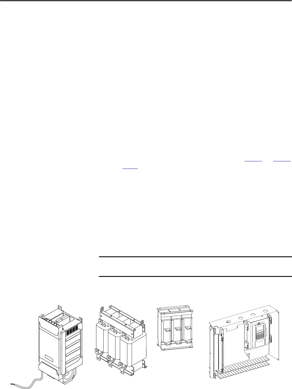
Standard Components (see illustrations below)
• Power Structure(s) - NFE converters and inverters (see Ta b le 1 and Table 2
on page 3
for the number of power structures provided with each frame
size)
• AC choke(s) - AC input drives only
• du/dt filter(s) - for frame 14 only (if ordered)
• Control frame with HIM assembly
• Control Cable Set - includes fiber optic cables and 24V connecting cable
(connects power structure and the control frame).
Standard length of 2.3 m (7.5 ft)
• Frames 12 and 14 include a fiber optic cable set for internal control
connections between power structures
All power cables, busbars, enclosures, enclosure options and mounting
hardware are customer supplied.
AC Choke Control Frame w/HIM Assembly
Control Cables
Power Structure du/dt Filter


