GOLDCUP CONTROLS CONTENTS
DESCRIPTION
PAGE
Ordering Code Pump Controls____________________________________________________________________________4
Motor Controls____________________________________________________________________________4
Table 1 Typical Characteristics______________________________________________________________________5
Code 1 Screw Adjustment Control. Disassy/Assy/Test___________________________________________________7
Figure 1 Screw Adjustment Control ___________________________________________________________9
Code 2A Cylinder Control, Disassy/Assy/Test ___________________________________________________________10
Figure 2A Cylinder Control__________________________________________________________________13
Code 2H 3 Position Cylinder Control. Disassy/Assy/Test __________________________________________________14
Figure 2H 3 Position Cylinder Control _________________________________________________________17
Code 40/4A Rotary Servo, Spring Ctd/Trimmer. Disassy/Assy/Test ____________________________________________18
Figure 4A Rotary Servo, Spring Ctd/Trimmer ____________________________________________________21
Code 4B/4C Rotary Servo, Brake and Bypass Valve. Disassy/Assy/Test_________________________________________22
Figure 4C Rotary Servo, Brake and Bypass Valve _______________________________________________26
Code 5A Electric Stroker. Disassy/Assy/Test ___________________________________________________________27
Figure 5A Electric Stroker __________________________________________________________________31
Figure 5A-1 Servo for Electric Stroker (Pump) __________________________________________________33
Figure 5A-2 Servo for Electric Stroker (Motor) __________________________________________________35
Code 5C Electric Stroker with Brake & Bypass Valve. Disassy/Assy/Test-_____________________________________36
Figure 5C Electric Stroker with Brake & Bypass Valve ____________________________________________41
Figure 5C-1 Brake and Bypass Valve for 5C Control- _____________________________________________43
Code 60 Hydraulic Stroker. Disassy/Assy/Test__________________________________________________________44
Figure 60 Hydraulic Stroker _________________________________________________________________47
Figure 60-1 Servo for Hydraulic Stroker _______________________________________________________48
Code 6A Hydraulic Stroker/Adj. Stops. Disassy/Assy/Test- ________________________________________________49
Figure 6A Hydraulic Stroker/Adj. Stops- _______________________________________________________53
Code 6B Hydraulic Stroker with Brake & Bypass Valve. Disassy;/Assy/Test ___________________________________54
Figure 6B Hydraulic Stroker with Brake & Bypass Valve- __________________________________________57
Figure 6B-1 Brake and Bypass Valve for 600 Series-_____________________________________________60
Code 6C Hydraulic Stroker with Brake & Bypass Valve/Adj. Stops Disassy/Assy/Test ___________________________61
Figure 6C Hydraulic Stroker with Brake & Bypass Valve/Adj. Stops __________________________________64
Code 7* Feedback for 700 Series HI-IQ Servovalve Control _______________________________________________66
SK-15045 Anti-Backlash Spring Installation for Feedback Controls __________________________________68
Figure 7 Feedback for 700 Series HI-IQ Servovalve Control________________________________________70
Code 8A Hydraulic Stroker. Disassy/Assy/Test__________________________________________________________71
Figure 8A Hydraulic Stroker Control-__________________________________________________________76
Figure 8A-1 Hydraulic/Electric Stroker Spool Assemblies- _________________________________________77
Code 8C Hydraulic Stroker with Brake & Bypass Valve. Disassy/Assy/Test ____________________________________78
Figure 8C Hydraulic Stroker with Brake & Bypass Valve- __________________________________________84
Figure 8C-1 Spool Assemblies for 8C & 9C Stroker w/Brake & Bypass Valve-__________________________85
Figure 8C-2 Brake Trimmer for 8C & 9C Stroker w/Brake & Bypass Valve-____________________________86
Code 9A Electric Stroker Control Disassy/Assy/Test _____________________________________________________87
Figure 9A Electric Stroker __________________________________________________________________93
Code 9C Electric Stroker with Brake & Bypass Valve. Disassy/Assy/Test-_____________________________________94
Figure 9C Electric Stroker with Brake & Bypass Valve-____________________________________________100
Code **4 Torque Limiter Option Disassy/Assy/Test_______________________________________________________101
S23-12298 Torque Limiter, One Side of Center,CW-B, CCW-A______________________________________105
S23-12299 Torque Limiter, Both Sides of Center_________________________________________________106
S23-12300 Torque Limiter, One Side of Center, CW-A, CCW-B _____________________________________107
Stroke Indicator Stroke Indicator Disassy/Assy________________________________________________________________108
S13-42064 Stroke Indicator _________________________________________________________________109
Seal Kits _______________________________________________________________________________________110
Conversions & Formulas __________________________________________________________________________________111
3
Note: Metric terms are noted in parentheses with decimal point designated by a period, as (2.25 Nm) equals 2,25 Newton meters.
T-1
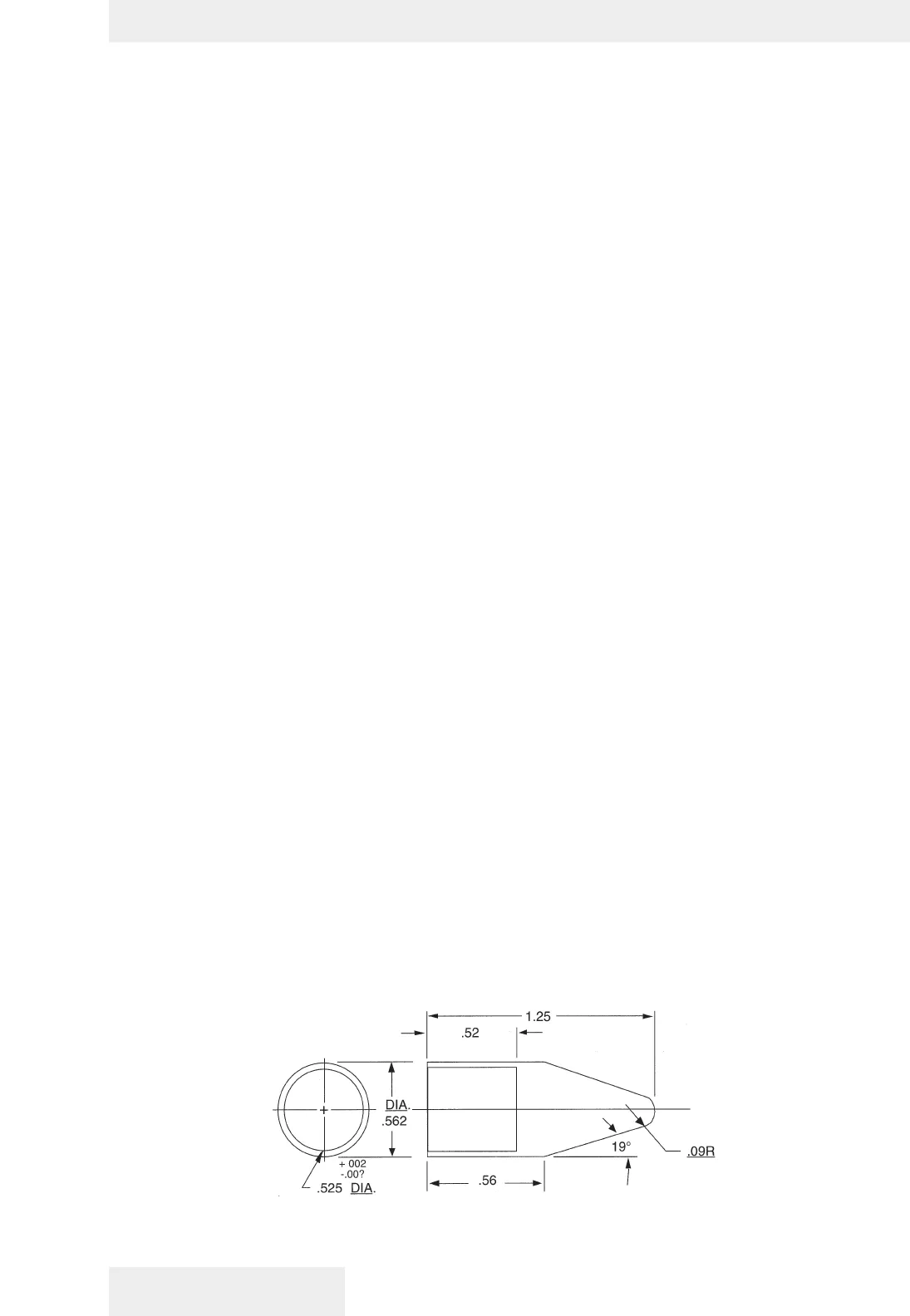
O-Ring installation tool