(2) Plug the black and red test leads into the
– and + input terminals, respectively.
(3) Measure the resistance by touching the
probes to the desired test points of the circuit.
(4) Read the measured resistance on the display.
If the resistance value is over range,
OL
will
appear on the display.
CHECKING THE INTEGRITY
OF A DIODE
(1) Turn the function switch to the (DAMP60)
or (DAMP68) position. Press the
SHIFT
button to select the diode check function.
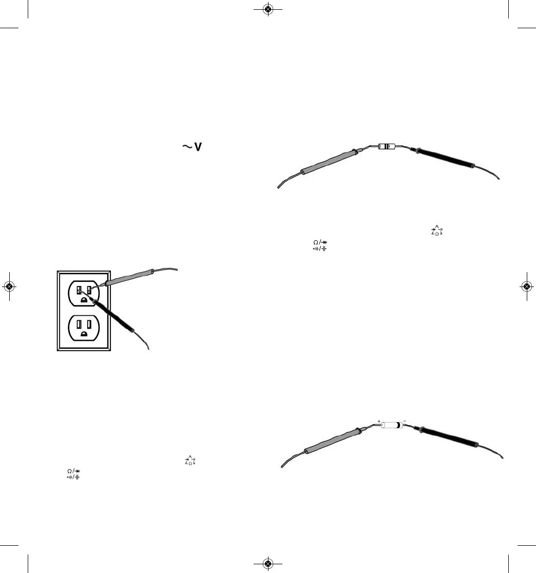
(2) Plug the black and red test leads into the
– and + input terminals, respectively.
(3) Connect the red test lead to the anode
(positive terminal) of the diode to be tested,
and the black test lead to its cathode
(negative terminal).
(4) Read the forward bias voltage value on the
display.
(5) If the polarity of the test leads is reversed,
OL
will appear on the display. This can be used to
distinguish the anode and cathode of a diode.
(6) A silicon diode typically has a forward bias
voltage of 0.7V. A germanium diode typically
has a forward bias voltage of 0.3V. A
0V
reading in both directions indicates a shorted
15
MEASURING AC VOLTAGE
Warning
Do not measure voltages higher than 600V AC or
internal damage will occur. If the applied voltage
is over 750V AC, the beeper will sound
continuously, indicating an over-range
measurement.
(1) Set the function switch to the position.
(2) Plug the black and red test leads into the
– and + input terminals, respectively.
(3) Measure the voltage by touching the probes to
the desired points of the circuit. With AC
voltage, the polarity of the test leads is not a
factor.
(4) Read the measured voltage on the display.
MEASURING RESISTANCE
Warning
To avoid electrical shock or damage to the meter
when measuring resistance or continuity in a
circuit, make sure the power to the circuit is
turned off and all capacitors are discharged.
(1) Turn the function switch to the (DAMP60)
or (DAMP68) position. Make sure power is
disconnected from the circuit to be measured.
Resistance measurement is the default
function for this function switch position on
both the DAMP60 and DAMP68.
14
RED TEST LEAD
BLACK TEST LEAD
RED TEST LEAD
BLACK TEST LEAD
RED TEST LEAD
BLACK TEST LEAD