PRODUCT OVERVIEW
Before using the transmitter and receiver together, learn how to make some basic
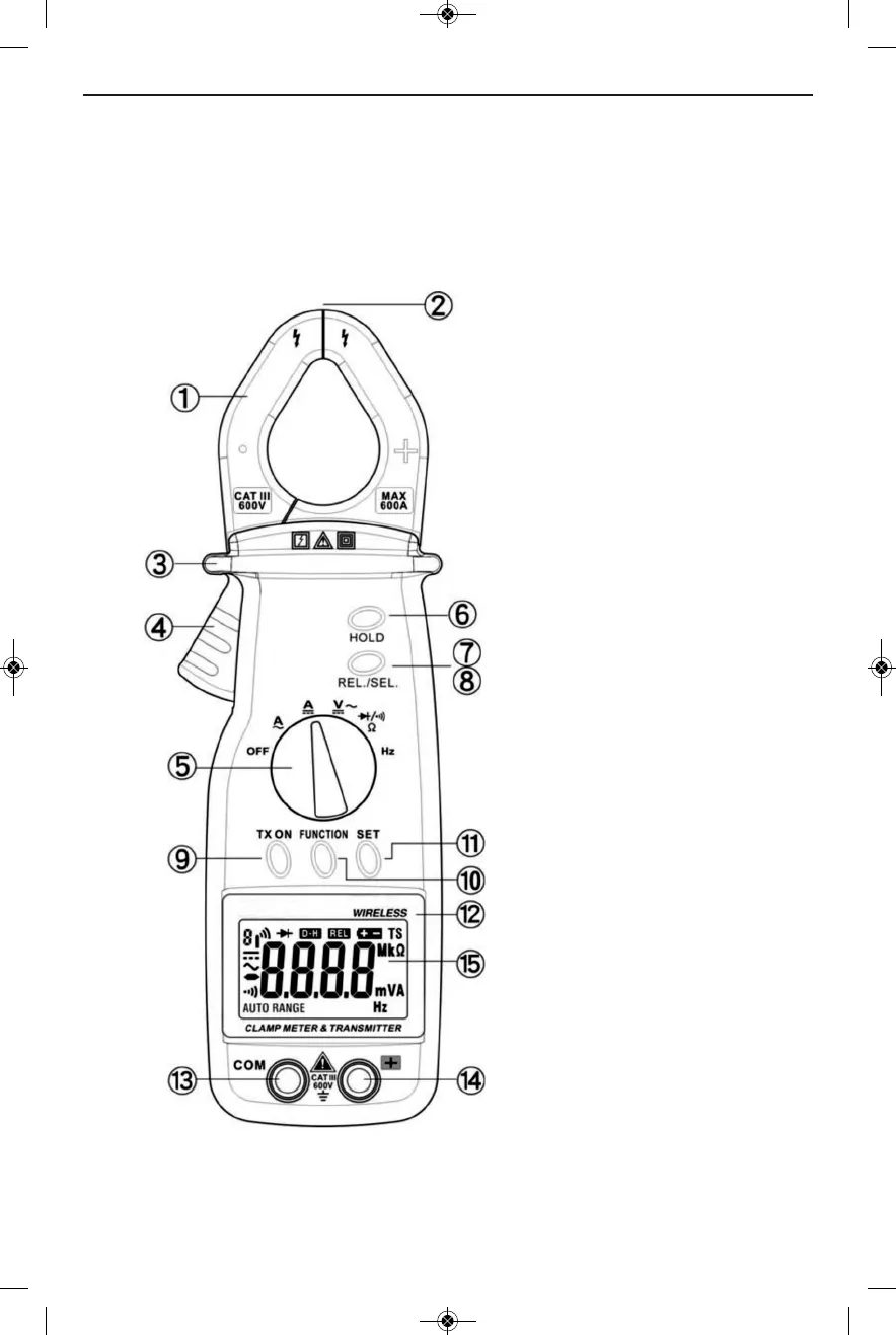
measurements using the transmitter unit alone. To begin, familiarize yourself with
Figures 1 and 2. Fig. 1 shows the transmitter unit’s controls, indicators and jacks. Fig. 2
shows the symbols used by the transmitter’s liquid-crystal display, as well as their
positions.
햲 Clamp
햳 Clamp tips/opening
햴 Guard ring
햵 Clamp trigger
햶 Function switch
햷 HOLD button
햸햹REL./SEL. button
햺 TX ON button
햻 FUNCTION button
햽 SET button
햾 Nameplate
햿 COM (negative or ground)
input jack
헀 쏋+ (positive) input jack
헁 Liquid-crystal display
Fig. 1. The transmitter’s controls, indicators and jacks
5