A “good” silicon diode should produce a reading of 0.5 to 0.7V. A “good” GE diode
should produce a reading of 0.2 to 0.3V. If the reading is close to “0”, the diode is short-
circuited. If the display reads “OL”, the diode is open-circuited.
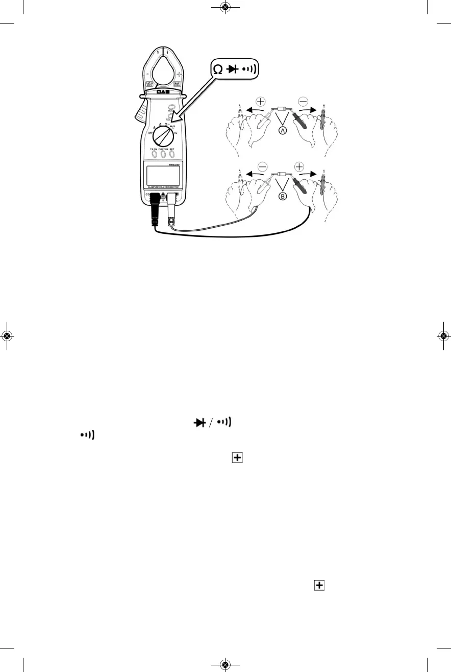
To perform a reverse-bias test, touch the tip of the red probe to the diode’s cathode
(- lead) and the tip of the black probe to the diode’s anode (+ lead), as shown in part B
of the figure above.
If the diode is “good”, the display will read “OL”. If it is “bad”, the display will show a
voltage level.
When you have finished using the clamp meter for diode testing, move the function
switch to the OFF position.
To check the continuity of a circuit between two points, first shut off all current
flowing through it to avoid damaging the multimeter in one of its most sensitive modes.
Move the function switch to the Ω / position and press the REL./SEL. button
until the symbol appears at the lower left of the display. Then plug the rubber-
covered end of the black probe into the COM jack of the transmitter and the
rubber-covered end of the red probe into the jack.
Then touch the metal ends of the black and red probes to the points between which you
wish to check for continuity. If there is continuity between the points, the beeper will
sound and the reading on the display will be less than 100Ω.
When you have finished making continuity checks, move the function switch to the OFF
position.
MEASURING FREQUENCY
To measure the frequency of an AC voltage or current, move the function switch to
the Hz position. Plug the rubber-covered end of the black probe into the COM jack of the
transmitter and the rubber-covered end of the red probe into the jack.
10
RED PROBE
BLACK PROBE