2.8 Service Power Inserter
1. The SPI box(es) are mounted on the shelf
support bracket.
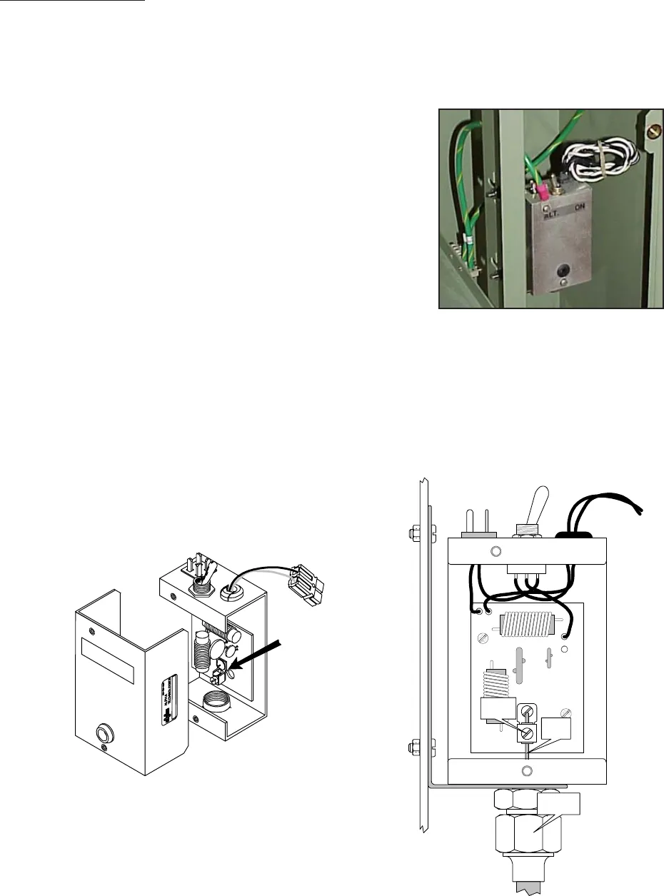
2. Remove the two screws on the face of the
SPI and lift off the cover to gain access to
the Seizure Screw Assembly. Loosen the
seizure Screw several turns so that the
stinger will pass through the clamp. (Fig 2-3)
3, Insert the Coaxial Termination into the output
port on the bottom of the SPI. Ensure that
the stinger goes through the Seizure Screw
Assembly. Tighten the Coaxial Termination.
4. Tighten the seizure screw to 35.0 Inch-Pounds.
Replace the SPI cover and screws.
Ensure that the switch on the top or the SPI is
in the ON position, the AUX position is used
only when an alternate power source is
connected to the SPI.
Seizure Screw
Assembly
Coax
Termination
Seizure
Screw
Coax
Stinger
2. Installation
20 031-106-C1-001 Rev. A
Fig. 13 Location of SPI
Fig. 12 Cable Connection
Fig. 11 Seizure Screw Assembly Location


