041-028-B1-001 Rev. B (09/2012)2
Total Power Solutions
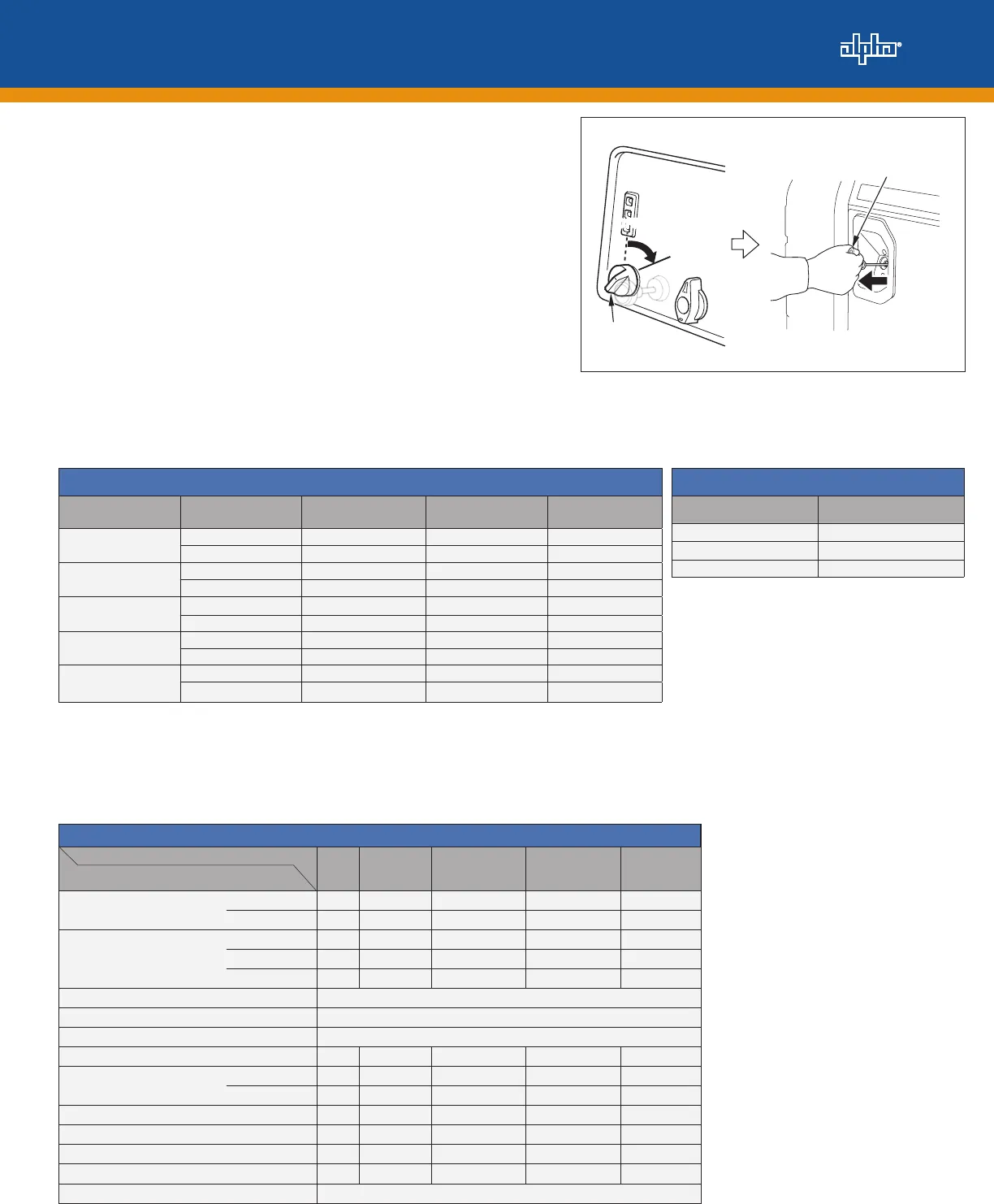
3. Turn the Engine Switch to the ON position (see Figure 2-2).
4. Pull the Starter Grip until you feel resistance, then pull
strongly in a straight line (see Figure 2-2).
Note: Pulling the Starter Grip at sharp angle to the
engine will prematurely wear out the cord. Do NOT let
the starter grip snap back against the engine.
5. If the choke was CLOSED to start the engine, gradually
push the choke in to the OPEN position as the engine
warms up.
Note: When the engine starts, DC output will begin
charging the UPS battery string automatically and the
output indicator (green) will go ON. If the UPS battery
string voltage is too low, the DC output will turn off. At
this time, the output indicator (green) will go OFF and
the overload indicator (red) will go ON (see Table 2-1).
Figure 2-2, Engine Switch and Starter Grip operation.
DC Output Coupler
Power
Coupler
DC Voltage
Selector
Switch
Voltmeter
Maintenance
Cover
No gap
Choke
Knob
Choke
Knob
CLOSED
O
OPPEENN
Choke
Knob
CLOSED
OPE N
Fuel Valve
Lever
ON
O
OFF
Engine
Switch
O
OFFFF
O
ONN
Starter Grip
Direction
to pull
Table 2-1, Battery Voltage alarm indicators.
Battery Voltage Alarm Indicators
Battery Voltage
1
Voltage Select
Switch Position
Output Indicator
(Green LED)
Overload Alarm
(Red LED)
Forced Output
2
0V to 2V
36V OFF OFF Not Available
48V OFF OFF Not Available
2V to 27V
36V OFF FLASHING ENABLED
48V OFF FLASHING ENABLED
27V to 42V
36V ON OFF Not Available
48V OFF FLASHING ENABLED
42V to 55V
36V OFF FLASHING Not Available
48V ON OFF Not Available
>56V
36V OFF FLASHING Not Available
3
48V OFF FLASHING Not Available
3
Run Time Table
Load Run Time (Hours)
25% 20
80% 10
100% 7.2
Table 2-2, Load to approximate run time.
(1)–All battery voltage measurements are ± 1V.
(2)–To enable forced output when the Overload Alarm LED is ashing, press the output button for at least 5 seconds. The Overload Alarm
LED stops ashing. Release the output button, and then press it again for at least ve seconds. The Output Indicator LED turns on steady,
and power output begins. The operator may then release the output button.
(3)–Engine shuts down after 1 second.
3.0 Maintenance Schedule
MAINTENANCE SCHEDULE
REGULAR SERVICE PERIOD
Note: Perform at every indicated month or oper-
ating hour interval, whichever comes rst.
Each
use
First month
or 20 hrs.
Every 3 months
or 50 hrs.
Every 6 months
or 100 hrs.
Every year or
300 hrs.
Engine Oil Check Level O
Change O O
Air Cleaner Check O
Clean O
2
Replace O
1
Canister Check Every 2 years (Replace if necessary)
3
Purge tube Check Every 2 years (Replace if necessary)
3
Charge tube Check Every 2 years (Replace if necessary)
3
Sediment Cup Check O
Spark Plug Check-adjust O
Replace O
Spark Arrester Clean O
Valve Clearance Check-adjust O
3
Combustion chamber Clean
Fuel tank and lter Clean O
3
Fuel tube Check Every 2 years (Replace if necessary)
2
(1)–Replace the paper air lter element only.
(2)–Service more frequently when used in dusty areas.
(3)–These items should be serviced by an authorized
AlphaGen dealer.
For commercial use, log hours of operation to
determine proper maintenance intervals. Failure to
follow this maintenance schedule could result in non-
warrantable damage.
Table 2-3, Battery Voltage alarm indicators.


