TPS3 09 Installation Instructions
Pre-Plan your installation. You need to accomplish the following:
• Meet all National and Local codes (NEC
®
Article 285 and UL
1449 address SPDs)
• Confirm System voltage to SPD voltage (120V SPD will fail
instantly on 240V, 277V, etc.)
• Mount SPD as close to panel or equipment as possible to keep
leads short (long leads hurt performance substantially)
• Ensure leads are as short and straight as possible, including
neutral and ground. If using a breaker, use a breaker position
that is close to the SPD and the panel’s neutral & ground
• If using a breaker, recommended breaker size is 30A due to
10 AWG conductor
• Make sure system is grounded per NEC
®
and clear of faults
before energizing SPD (inadvertent system problem may fail
SPD).
• Never Hi-Pot test Any SPD (will prematurely fail SPD)
• Do not install the TPS3 09 through the bottom of a NEMA
3R panel. Dripping water will prematurely fail the SPD.
1. Use voltmeter to check voltages and ensure correct SPD. See Data
Sheet for specs & wire-outs
2. Determine Mounting location – weather resistant equipment
may be required
3. If SPD has optional Dry Contact and Flush Mount Kit, pre-plan
their installation. See Figures 4&6. (If flush mounting, be careful
to not drop SPD into wall)
4. Remove power from panel/source. Confirm panel/source is
deenergized.
5. Identify breaker location and SPD location. Position SPD such that
LEDs are best visible.
6. Mount SPD – weather resistant applications require additional
sealing, o-rings, etc. (not included)
- Remove an appropriately sized knockout from panel.
- Connect conductors as appropriate – short and straight as possible
(Hi-Legs are Phase B)
- Note that the metallic connection hub is not grounded within the SPD
and proper grounding requires connection of the green conductor
ground.
7. Label or mark conductors as appropriate (neutral: white, ground:
green, energized: black, hi-leg: orange)
8. Make sure system is bonded per NEC
®
and is clear of hazards or
faults before energizing (N-G bonding not per NEC
®
will fail SPDs:
#1 cause of SPD failures)
9. Energize and confirm proper operation of green LED indicators
and/or options.
A
B C
GN
BREAKER
• Use closest breaker to SPD
• Locate SPD close to intended
breaker
• Keep Leads Short as Possible
• Avoid Sharp Bends
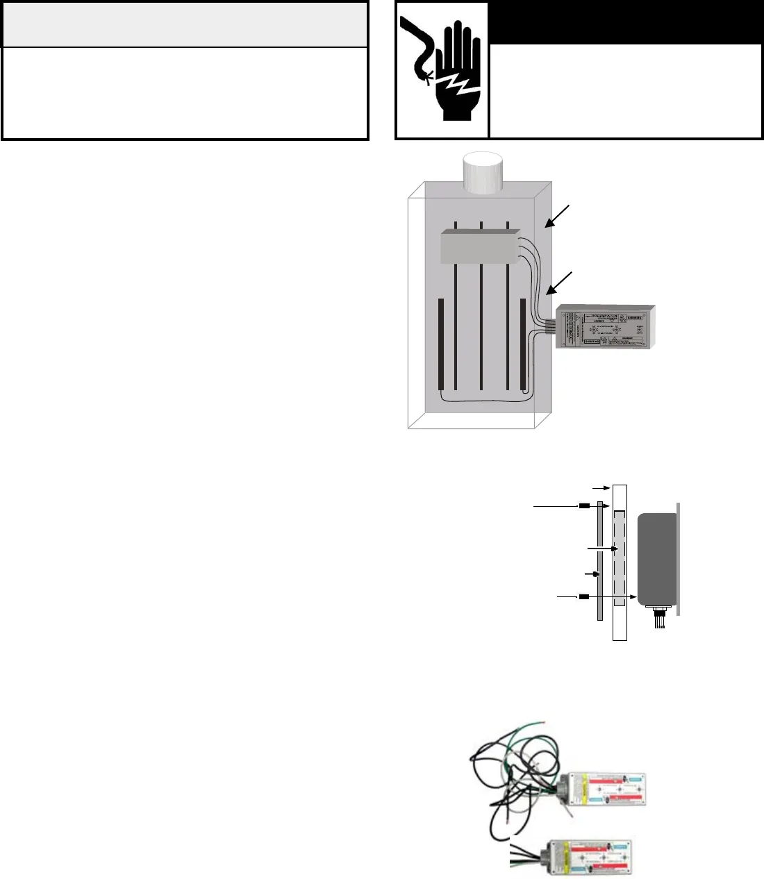
Figure 4: Typical Flush Mount Installation
Phase, Ground,
and Neutral Wires
SPD
Mounting Screws
(4 places, through mountingplate into mounting
surface, screws not provided)
Flush Mount Kit Screws
(8-32 x 5/8” Thread Cutting, 4 places, through
plate into SPD)
Mounting Surface
Removed Material
Flush Mount Plate
Figure 5: Lead Lengths
Leads: Short & Straight
Cut Excess; Do Not Coil or Loop
• CUT OFF EXCESS
LENGTH
• DO NOT LOOP OR
COIL
• SHORT &
STRAIGHT
X
Not
Good
p
Good
CONDUCTING DIELECTRIC AND/OR
HI-POTENTIAL TESTING WILL CAUSE
INTERNAL DAMAGE TO TPS3 UNIT.
Do not perform dielectric or high potential
tests with the TPS3 unit installed.
CAUTION
V
Hazardous voltage.
Will cause death or serious injury.
Keep Out.
Qualied personnel only.
Disconnect and lock off all power before
working on this equipment.
V DANGER


