RLX-IFHE ♦ RadioLinx Industrial Wireless Installing the Radios
RadioLinx® Industrial Frequency Hopping Ethernet Radios User Manual
ProSoft Technology, Inc. Page 59 of 109
November 19, 2013
Ethernet Cable Specifications
The recommended cable is category 5 or better. A category 5 cable has four
twisted pairs of wire that are color-coded and cannot be swapped. The radio
uses only two pairs. One pair uses pins 1 and 2, and the second pair uses pins 3
and 6.
Use a straight-through cable when connecting the radio to an Ethernet hub or
a 10/100 Base-T Ethernet switch. Straight-through cables are used in most
cases.
Use a cross-over cable when connecting the Ethernet radio directly to any
device that is NOT a switch or a hub (for example, a direct connection to a
PC, PLC, or printer).
Ethernet cabling is like U.S. telephone cables, except that it has eight
conductors. Some hubs have one input that can accept either a straight-through
or crossover cable, depending on the switch position. In this case, you must
ensure that the switch position and cable type agree.
Refer to Ethernet cable configuration (page 59) for a diagram of how to configure
Ethernet cable.
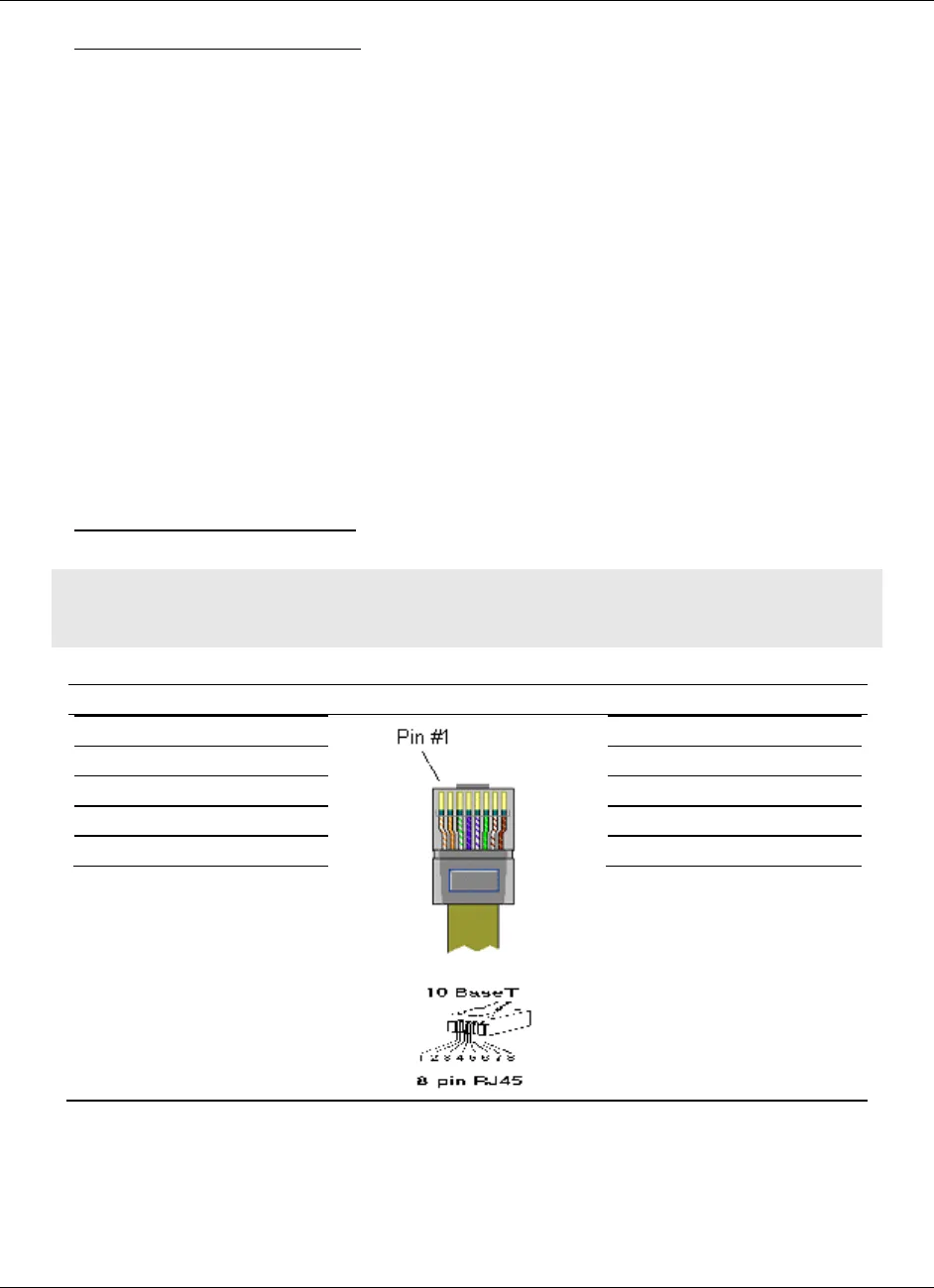
Ethernet Cable Configuration
Note: The standard connector view shown is color-coded for a straight-through
cable.


