Grayhill, Inc. • 561 Hillgrove Avenue • LaGrange, Illinois 60525-5997 • USA • Phone: 708-354-1040 • Fax: 708-354-2820 • www.grayhill.com
Optical and Mechanical
Encoders
Mechanical Encoders
Forpricesanddiscounts,contactalocalSalesOfce,anauthorizedlocalDistributororGrayhill.
OPTIONS
Adjustable Stops
Set and reset stops to limit rotation. All
dimensions are the same as for xed stop
switches. Switches are shipped with the stop
blades located to limit rotation to 11 switch
positions.Forcontinuousrotation,removeboth
blades. For limited rotation, remove the 2nd
(clockwise) blade and move it to the hole located
between the positions shown in the Truth Tables.
Removal of a plastic washer provides access to
thebladesandslots.Adjustablestopversions
are available in unsealed styles only.
Shaft and Panel Seal
Switches are available in sealed or unsealed
styles.Forsealedstyle,thepanelissealedby
an o-ring at the base of the bushing. The shaft
issealedbyano-ringinsideofbushing.After
the switch is mounted, seals do not alter the
dimensions of the unsealed style.
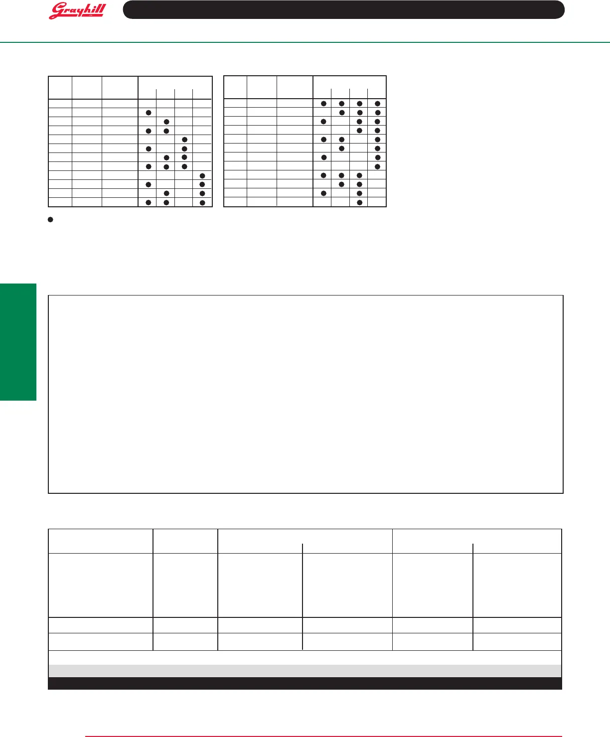
Dec. Switch 2nd Output Terminal
No. Pos'n.* Pin** 1 2 4 8
0 1 4-5
1 2 5-6
2 3 6-7
3 4 7-8
4 5 8-9
5 6 9-10
6 7 10-11
7 8 11-12
8 9 12-1
9 10 1-2
10 11 2-3
11 12 3-4
Indicates contact made to common
* The switch position number is the terminal location opposite the shaft flat; it is
not the same as the decimal number.
**Tolimitanadjustablestopswitchtothedecimalnumbershown,insertthe
secondpinintheholelyingbetweenthe2switchpositionsindicated.
TRUTH TABLES
Binary Code Decimal Binary Code Decimal Complement
Electrical Rating
Rated:Tomakeand break 125mA30Vdc
resistiveloadfor25,000cyclesofoperation.
Cycle:(1cycle=360°rotationandreturn)Test
conditions are standard atmospheric pressure,
25°Cand68%relativehumidity.
Contact Resistance: 20 milliohms initially,
300milliohmsmaximumafterlife
Insulation Resistance: 50,000 megohms
initially,10,000megohmsafterlife
Voltage Breakdown:500Vacbetween
mutually insulated parts
SPECIFICATIONS
Type Of Maximum No. BCD Output BCD Complement
Switch Of Positions Unsealed Sealed Unsealed Sealed
7 513360-7 513374-7 513361-7 513375-7
8 513360-8 513374-8 513361-8 513375-8
FixedStop 9 513360-9 513374-9 513361-9 513375-9
10 513360-10 513374-10 513361-10 513375-10
11 513360-11 513374-11 513361-11 513375-11
12 513360-12-F 513374-12-F 513361-12-F 513375-12-F
ContinuousRotation 12 513360-12-C 513374-12-C 513361-12-C 513375-12-C
AdjustableStop 12 513385 ——— 513384 ———
The-Csufxindicatescontinuousrotation.The-Fsufxindicatesaxedstopbetweenpositions1and12.
ORDERING INFORMATION
Materials and Finishes
Bases: Thermoset plastic
Detent Rotor: Nylon
Shaft, Stop Blades, Stop Arm, Thrust Washer
And Retaining Ring: Stainless steel
Detent Balls: Steel, nickel-plated
Bushing: Zinc, Tin-zinc-plated
Detent Spring: Stainless steel
Common Terminals and Rings: Brass, gold
plate.00003"minimumoversilverplate.0003"
minimum
Terminals: Brass with silver contact surface,
gold-plated.00003"
Rotor Contact: Berillium copper with silver
contact surface
Shaft And Panel Seal: Silicone rubber
Mounting Hardware:Onemountingnut,.089"
thickby.375"acrossats,andoneinternaltooth
lockwasher are supplied with the switch.
Additional Characteristics
Contact Type: Wiping contacts
Shaft Flat Orientation: Switch position is
denedasthatpositionthatisoppositetheshaft
flat. The location of the contacts in relation to the
shaft flat is shown on the circuit diagram.
Terminals: Only the active position terminals,
as shown in the circuit diagram are supplied
with the switch. All common terminals are
supplied.
Stop Strength:7.5in-lbsminimum
Rotational Torque:8to16in-oz
Bushing Mounting: Required for these
switches
Maximum Mounting Torque:15in-lbs.
Dec. Switch 2nd Output Terminal
No. Pos'n.* Pin** 1 2 4 8
0 1 12-1
1 2 1-2
2 3 2-3
3 4 3-4
4 5 4-5
5 6 5-6
6 7 6-7
7 8 7-8
8 9 8-9
9 10 9-10
10 11 10-11
11 12 11-12


