Appendix M ASM8, ASM8+, and GASM wiring chart 243
BCM50 Installation and Maintenance Guide
Appendix M
ASM8, ASM8+, and GASM wiring chart
Analog telephony devices, such as single line telephones, modems and Fax machines, connect to
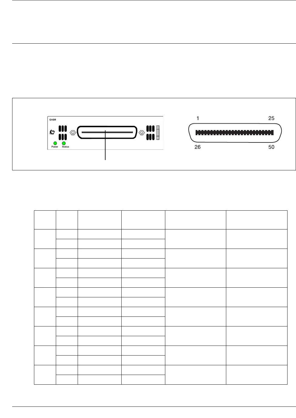
the Analog Station Module (ASM) through the RJ-21 connector on the front of the media bay
module. See the figure ASM RJ-21 connector on page 243.
Figure 99 ASM RJ-21 connector
The table ASM RJ-21 connector wiring on page 243 lists the wiring details for the RJ-21
connector on the ASM.
Table 53 ASM RJ-21 connector wiring (Sheet 1 of 2)
Set Pin Connection Wire color
Default DN on
Expansion port 1
Default DN on
Expansion port 2
1
26 Tip White-Blue
237 269
1 Ring Blue-White
2
27 Tip White-Orange
238 270
2 Ring Orange-White
3
28 Tip White-Green
239 271
3 Ring Green-White
4
29 Tip White-Brown
240 272
4 Ring Brown-White
5
30 Tip White-Slate
241 273
5 Ring Slate-White
6
31 Tip Red-Blue
242 274
6 Ring Blue-Red
7
32 Tip Red-Orange
243 275
7 Ring Orange-Red
8
33 Tip Red-Green
244 276
8 Ring Green-Red
RJ-21 pin out
RJ-21 connector
GASM


