Appendix F DTM wiring chart 221
BCM50 Installation and Maintenance Guide
Appendix F
DTM wiring chart
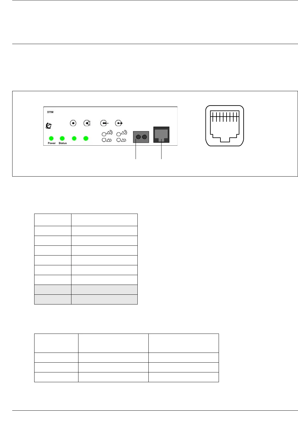
The digital telephone line connects to the Digital Trunk Module (DTM) through the RJ-48c jack
on the front of the media bay module (MBM). See the figure DTM RJ-48C port on page 221.
Figure 92 DTM RJ-48C port
The table DTM RJ-48c port wiring on page 221 and the table DTM line numbering on page 221
list the wiring details for the RJ-48C port.
Table 40 DTM RJ-48c port wiring
Pin Signal
1 Receive Ring
2 Receive Tip
3 Receive Shield
4 Transmit Ring
5Transmit Tip
6 Transmit Shield
7 No connection
8 No connection
Table 41 DTM line numbering
Line type
Default line numbers on
Expansion port 1
Default line numbers on
Expansion port 2
T1 065 – 088 095 – 118
PRI 065 – 087 095 – 117
E1 065 – 094 095 – 124
1 2 3 4 5 6 7 8
RJ-48C jack
RJ-48C pin out
DTM
Bantam jack


